
Time-resolved Photoluminescence
Time-resolved Photoluminescence (TRPL) measurements are used to analyze emitter lifetimes. The measurements can be replicated in Bumblebee in order to investigate the effect of excitonic processes on singlet/triplet populations.
Note
A pre-made project file is available for this tutorial.
Create Materials
In this tutorial, we will look at the TRPL response of a thermally-activated delayed fluorescence (TADF) emitter: DPA4.
Emitter
For this tutorial, we will use experimental parameters for the DPA4 emitter lifetime. We use the TADF Dye template and create a new material.
We set a HOMO level of -5.6 eV and and a LUMO level of -1.5 eV. The singlet energy level is set to 3.1 eV and the triplet energy level is set to 1.7 eV.
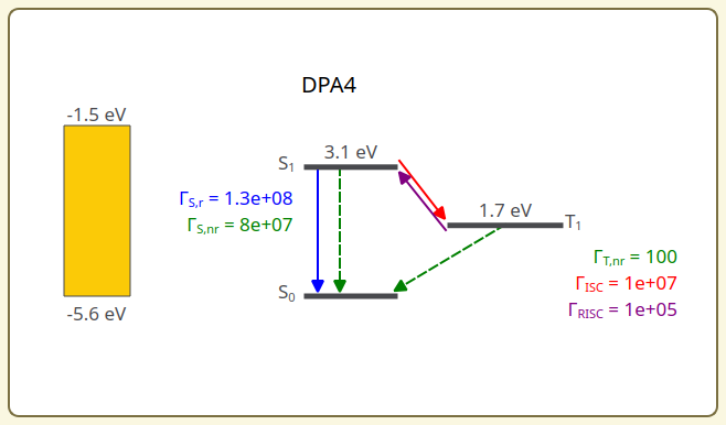
Fig. 84 Jablonski diagram of DPA4
In the photophysics section, we set the singlet radiative decay rate to \(1.3\cdot{}10^{8}\,\textrm{s}^{-1}\). The non-radiative singlet decay rate is set to \(8.0\cdot{}10^{7}\,\textrm{s}^{-1}\). A small non-radiative triplet decay rate of \(10^{2}\,\textrm{s}^{-1}\) is added to deal with residual triplet species in the TRPL. ISC and rISC rates will be kept at the default values.
Host
Zeonex is used as the host material. Zeonex is a wide-bandgap material that is used to optically isolate the excitonic emission.
We will model this behavior by setting a HOMO level of -7 eV and a LUMO level of 0 eV. The photophysical rates are all set to zero. Remaining parameters will be kept default.
Create a Composition
We will simulate TRPL for a thin film containing DPA4 in a Zeonex matrix.
Create a new composition on the Compositions page
Add the Zeonex host and set the fraction to 0.5
Add the DPA4 emitter and set the fraction to 0.5
This mixture will be used to compare against experimental measurement.
Create a Stack
We will create a thin film device by adding a single 30 nm layer of our host-guest system.
In order to mimic the single-pulse excitation of the TRPL setup, we will use the dopants feature to generate an initial exciton population.
In the stack editor, we use the  button in the Dopants table to add a new species. We select DPA4 as the absorbing material and set the dopant type to Singlet. A dopant fraction of 0.3 is used to generate a 30% singlet density, accounting for optical incoupling losses during pulsed illumination.

Fig. 85 Initial singlet density specified in the stack editor
Create a Parameter Set
To configure a TRPL simulation, we will load the Photoluminescence template for our parameter set. This will configure a bulk simulation, allowing us to observe the response of the material without worrying about interactions with the electrodes. TRPL analysis in the simulation output will also be set automatically.
Tip
In order to make the tutorial run more quickly, we can choose to simulate a smaller volume, at the cost of a higher noise signal at longer response times. To do this, navigate to the Volume tab and change the width and breath of the simulation volume to 30 nm each.
Starting the Simulation
For this tutorial, we will set up a new simulation to run at 0 V. By default, 5 trajectories will be generated.
We do not need to change any settings in the Simulation page. We use File → Save and File → Run to start the simulation using the default configuration.
Simulation Output
We can view the transient photoluminescence rate from the Sweep → Photoluminescence → Transient Luminescent Decay Rate section of BBresults. A bi-exponential decay is seen, typical of TADF materials.
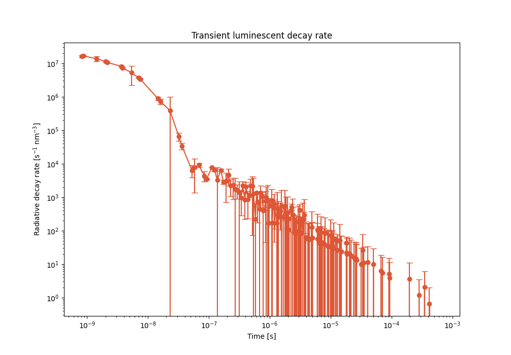
Fig. 86 Transient photoluminescence of the DPA4/Zeonex matrix
The first shoulder in the time-resolved emission profile emerges through prompt fluorescence from the initial singlet population. Due to the fast fluorescence rate, the singlet population is gradually depleted throughout the first 100 ns. The delayed fluorescence component follows from the residual triplet population. These triplets are converted back to the emissive singlet state through the slow rISC process, resulting in delayed emission up to around 0.1 ms. These characteristics match quite closely to the experimental TRPL. [1]
The source of singlet-triplet interconversion can be analyzed by looking at the excitonic events distribution (Device → Event Distribution).
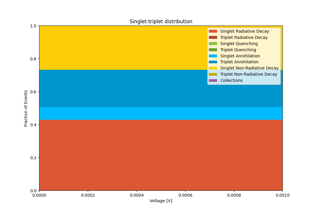
Fig. 87 Excitonic event distribution during TRPL
Due to the high initial singlet density, singlet-singlet annihilation (SSA) results in a partial loss of excitons following the PL pulse. Triplet-triplet annihilation (TTA) appears to be the dominant pathway for removal of triplet species from the device. The annihilation product for TTA generates a new singlet state, resulting in an enhancement of the delayed fluorescence.
The change in the triplet population can be seen in the Sweep → Photoluminescence → Transient Triplet Population graph.
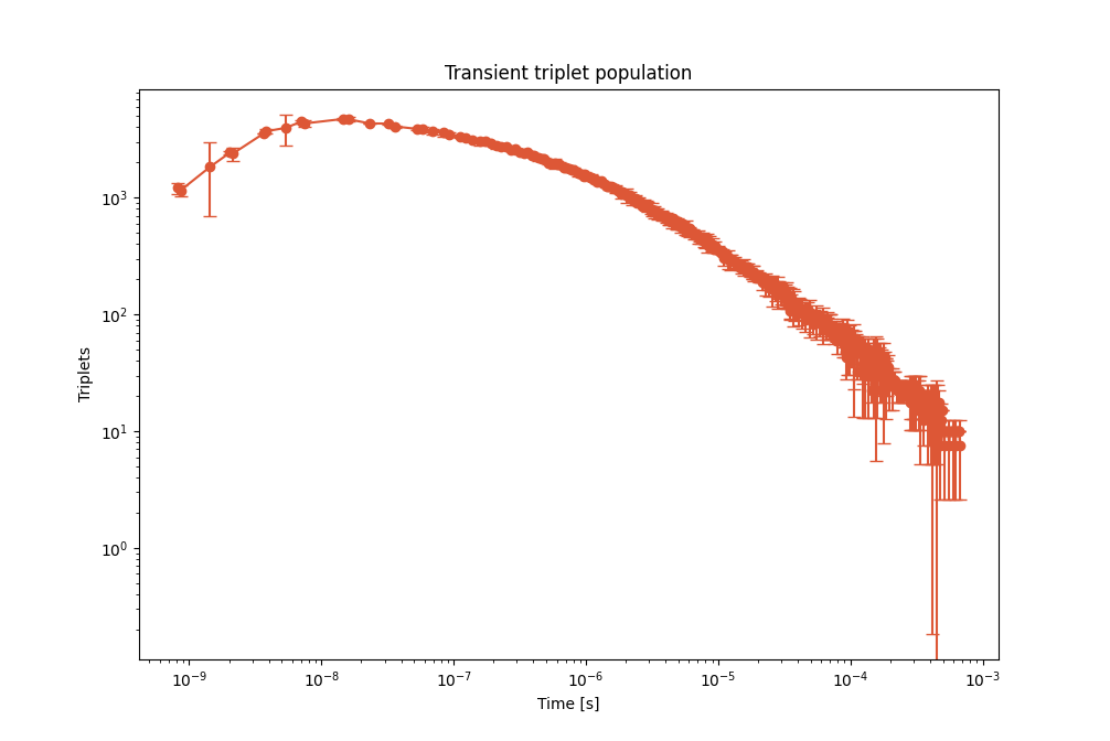
Fig. 88 Transient triplet population inside the DPA4 device
The initial increase in triplet density originates through ISC from the pulsed singlet population. Once the singlets have been mostly depleted, the residual triplet density slowly declines as delayed fluorescence proceeds. The non-linear decay in the logarithmic triplet density is indicative of a dual upconversion mechanism involving both rISC and TTA.
See also
The pulsed illumination can also be included directly into the simulation window to account more accurately for e.g. initial SSA. Check out the transient response tutorial for more details.