CO Oxidation on Pt(111)
Note: This tutorial is intended for AMS2026 with access to the UMA-S-1.2-OC25 machine learning potential.
This tutorial will teach you how to:
optimize bulk Pt and construct a Pt(111) slab,
identify the common adsorption sites on Pt(111),
build and relax O*, O2*, CO*, and CO* + O2* structures,
compare binding energies with literature trends, and
set up a simple NEB reaction path for CO* + O2* → CO2 + O*.
The scientific context is the catalytic oxidation of CO on Pt(111). In particular, we use the same qualitative questions discussed by Eichler and Hafner in Ref. [1]: can coadsorbed CO stabilize molecular oxygen on Pt(111), and which coadsorbed geometry is the more plausible precursor for oxidation?
Warning
The adsorption energies reported in Ref. [1]: are based on early GGA-level density functional theory and should be considered outdated by current standards. Significant methodological advances—such as dispersion-corrected DFT, meta-GGA functionals, and higher-level electronic structure methods—have since improved both the accuracy of adsorption energies and the prediction of adsorption sites (notably for CO on Pt(111)). In this tutorial, the reference is used purely for illustrative purposes to demonstrate the workflow for computing binding energies. The UMA OC25 model employed here is trained at the PBE-D3 level of theory, and therefore we expect results that are broadly consistent with GGA + dispersion calculations, and qualitatively comparable to those reported in the cited work, though not necessarily aligned with modern benchmark values or experimental adsorption energies.
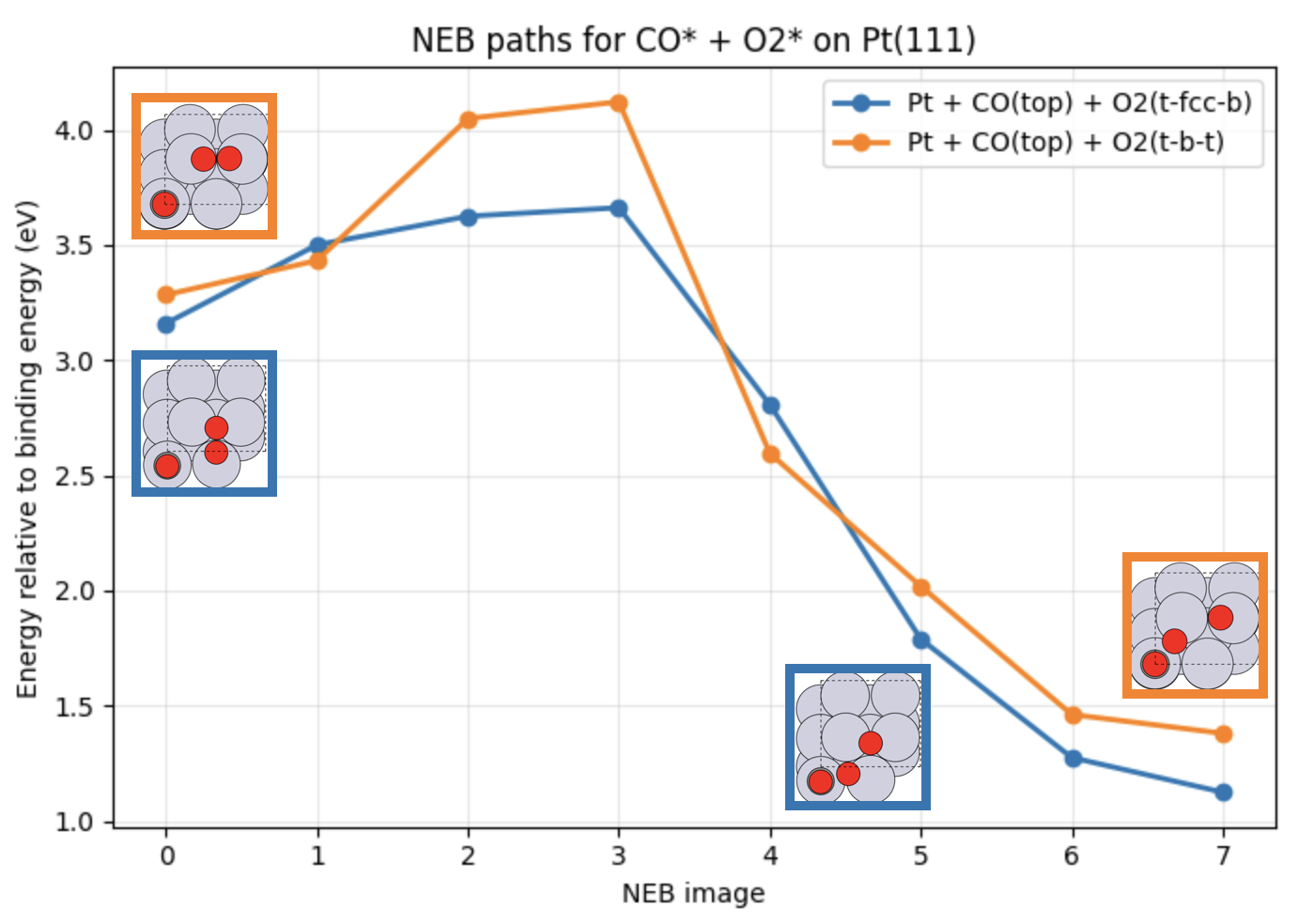
Fig. 28 Calculated reaction pathways corresponding to CO* + O2* → CO2 + O* with O2 adsorbed at different surface sites. The reaction energies are relative to the binding energy of CO and O2 on Pt(111).
This tutorial is the GUI companion to CatalysisReaction.ipynb.
Note
The GUI workflow is slightly more manual than the notebook workflow. In particular, naming adsorption sites, constructing many related structures, and comparing energies across several jobs requires more bookkeeping in the GUI. It is worth keeping a small table with job names, final energies, and short notes for each structure.
Introduction
Pt(111) is a standard model surface for heterogeneous catalysis, and CO oxidation on Pt is one of the classic benchmark reactions in surface science. A useful way to study such a system computationally is to break the problem into a sequence of manageable steps:
optimize the bulk reference,
build the slab,
identify adsorption sites,
test adsorbate and coadsorbate geometries,
compare relaxed adsorption energies, and
define a reaction path between selected initial and final states.
In this tutorial, we use a 2 x 2 Pt(111) slab and examine:
atomic O at fcc and hcp sites,
CO at top and bridge sites,
molecular O2 in two adsorption motifs, and
two CO* + O2* coadsorbed structures.
The final section shows how to define a practical NEB path in the GUI from the relaxed coadsorbed states.
Part A: Bulk Pt Reference
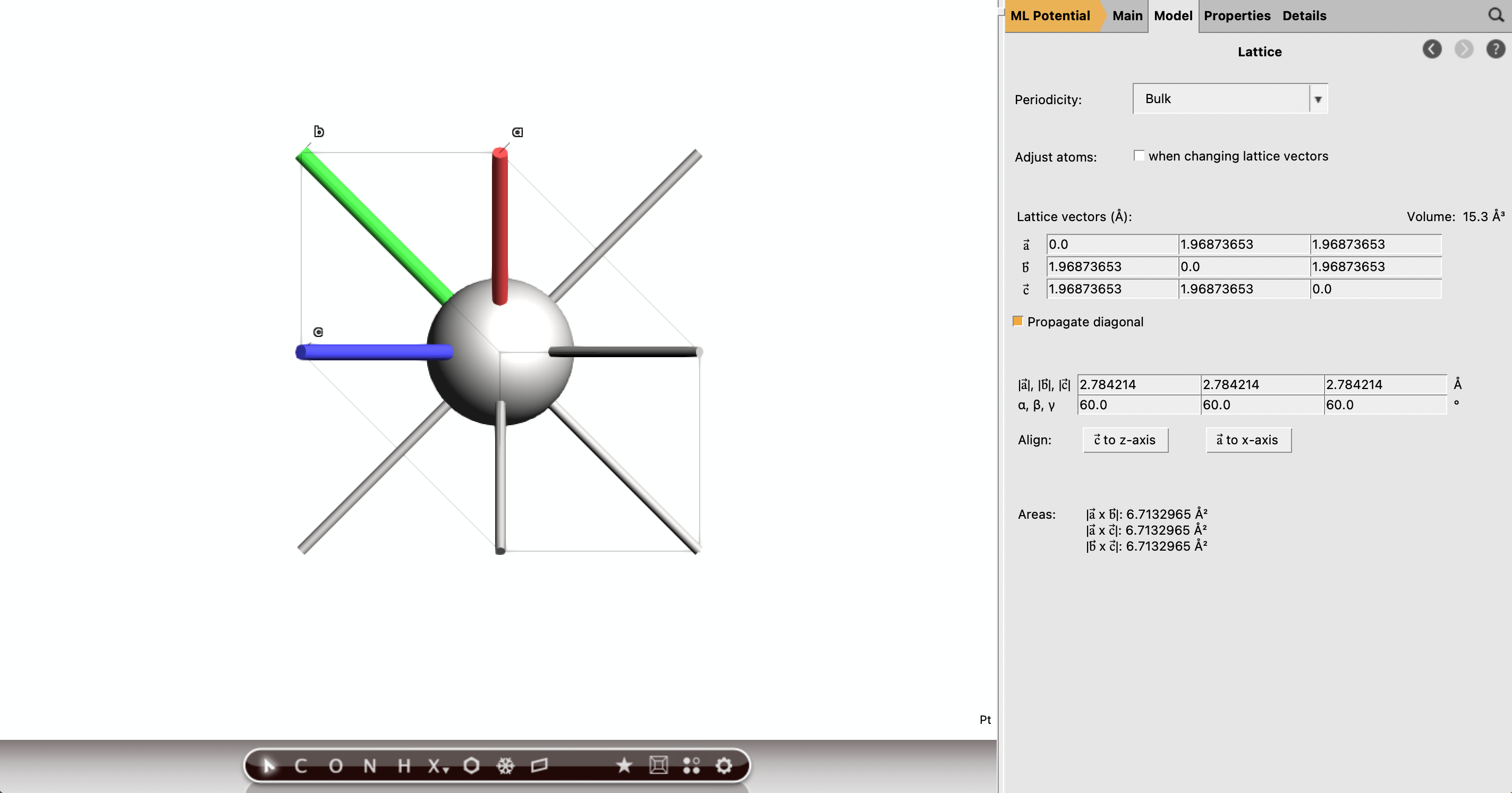
Before building the surface slab, optimize bulk fcc Pt so that the slab uses a lattice parameter consistent with the chosen model chemistry.
Set up and run bulk Pt
 →
→ 
Pt_fcc_relaxNote
When the run is finished, open the input and click Update Molecule next the Task. Select Model → Lattice and record the optimized lattice parameter from the output. You will use it when constructing the Pt(111) slab. We found 2.784214 Å.
Part B: Build the Pt(111) Slab
Next, construct a Pt(111) slab using the optimized bulk lattice parameter.
Build the slab
→ Pt111_2x2_baseNote
At this stage you do not need to run a job yet, we plan to reuse this structure as a template for all adsorption systems.
Part C: Identify the Adsorption Sites
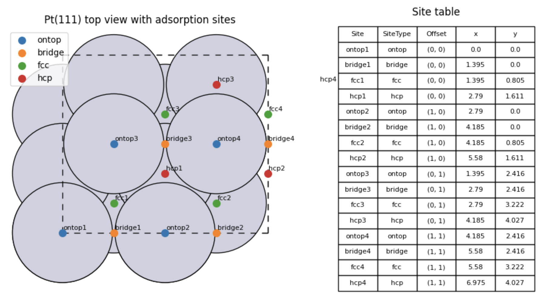
The common adsorption sites on Pt(111) are top, bridge, fcc hollow, and hcp hollow.
Recommended workflow for site identification
Pt111_2x2_base structureTip
Select the top layer, Model → Regions and call it top. Deselect all atoms, select the second sub layer, create the region layer1. Select the third layer, call it layer2. Select the bottom layer, call it bottom. Each region should be made of Pt4 which appears next the region name. Now looking from the top, you will have a better view of the structure and you can identify the various sites.
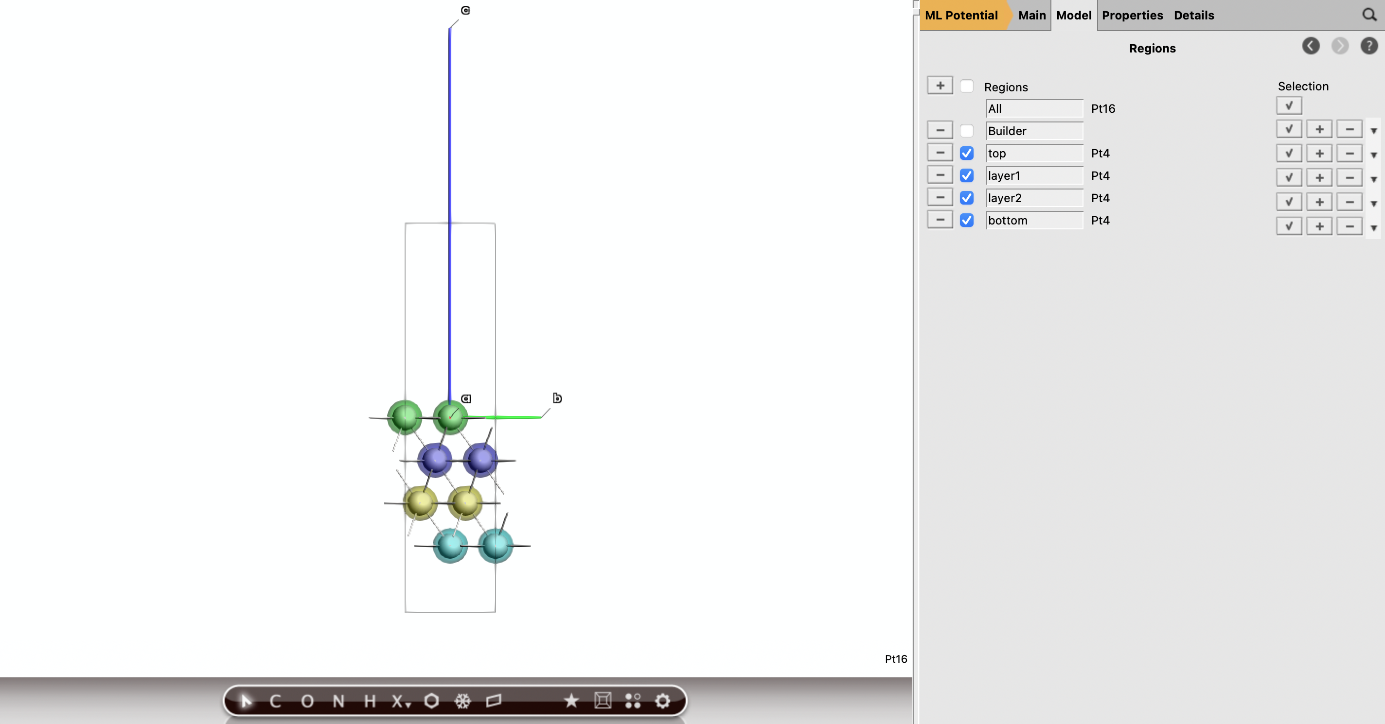
Fig. 29 Side view of the Pt(111) slab to appreciate the various layers and corresponding regions.
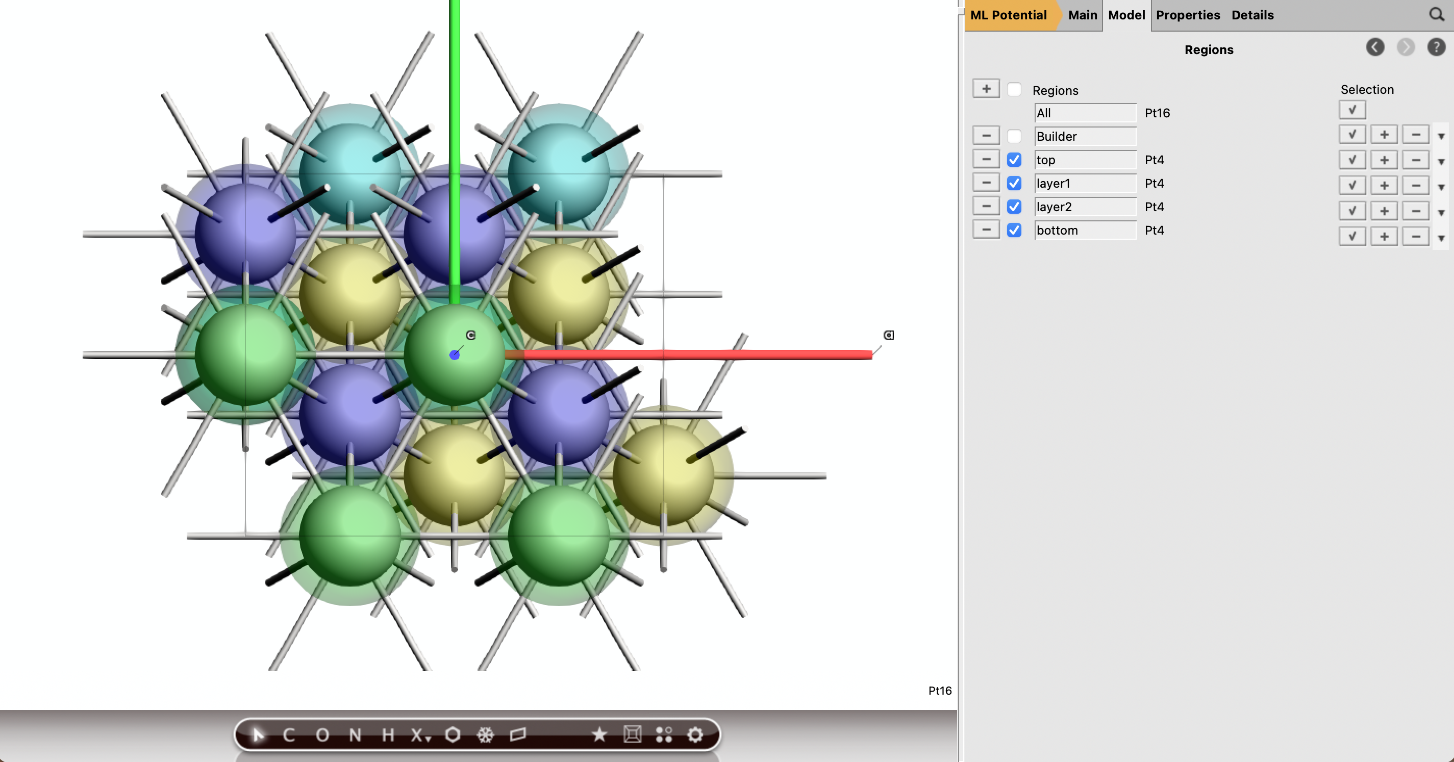
Fig. 30 Top view of the Pt(111) slab to appreciate the various adosprtion sites.
Tip
You can easily switch between yz, xz, and xy projections with the cmd+1, cmd+2, and cmd+3 shortcuts (use ctrl instead of cmd on a Windows machine), respectively.
Part D: Build the Adsorbed Structures
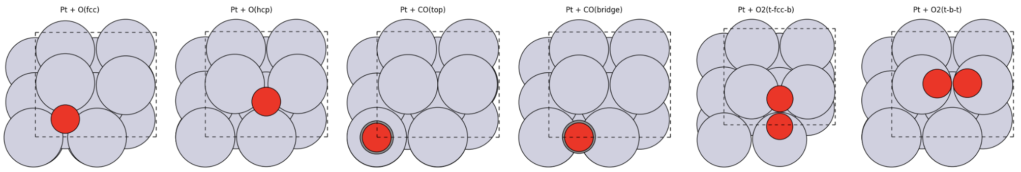
The next step is to create a small library of adsorbate structures from the slab:
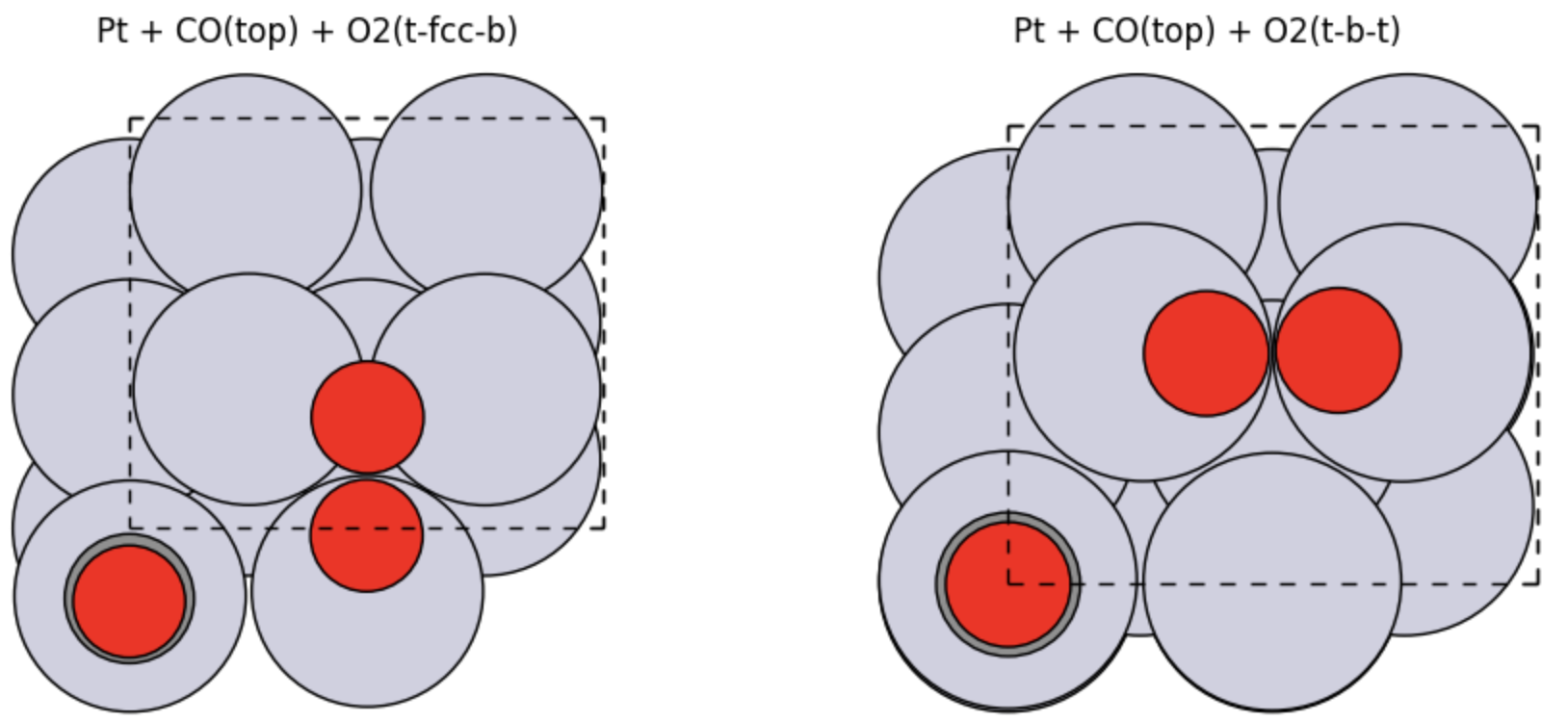
Pt + O(fcc)Pt + O(hcp)Pt + CO(top)Pt + CO(bridge)Pt + O2(t-fcc-b)Pt + O2(t-b-t)Pt + CO(top) + O2(t-fcc-b)Pt + CO(top) + O2(t-b-t)
Build atomic oxygen structures
1.2 to 1.3 Å above the top Pt layerads_sites_o_fcc_2x2ads_sites_o_hcp_2x2Build CO structures
1.8 to 1.9 Åads_sites_co_top_2x2ads_sites_co_bridge_2x2Build O2 structures
1.3 Åads_sites_o2_t_fcc_b_2x2ads_sites_o2_t_b_t_2x2Build the coadsorbed structures
ads_sites_o2_t_fcc_b_2x2CO(top)ads_sites_coads_t_fcc_b_2x2ads_sites_o2_t_b_t_2x2ads_sites_coads_t_b_t_2x2Tip
Keep the atom ordering as consistent as possible when you later want to use these structures for NEB. In particular, it is helpful if the slab atoms stay unchanged and new adsorbate atoms are added in a reproducible order.
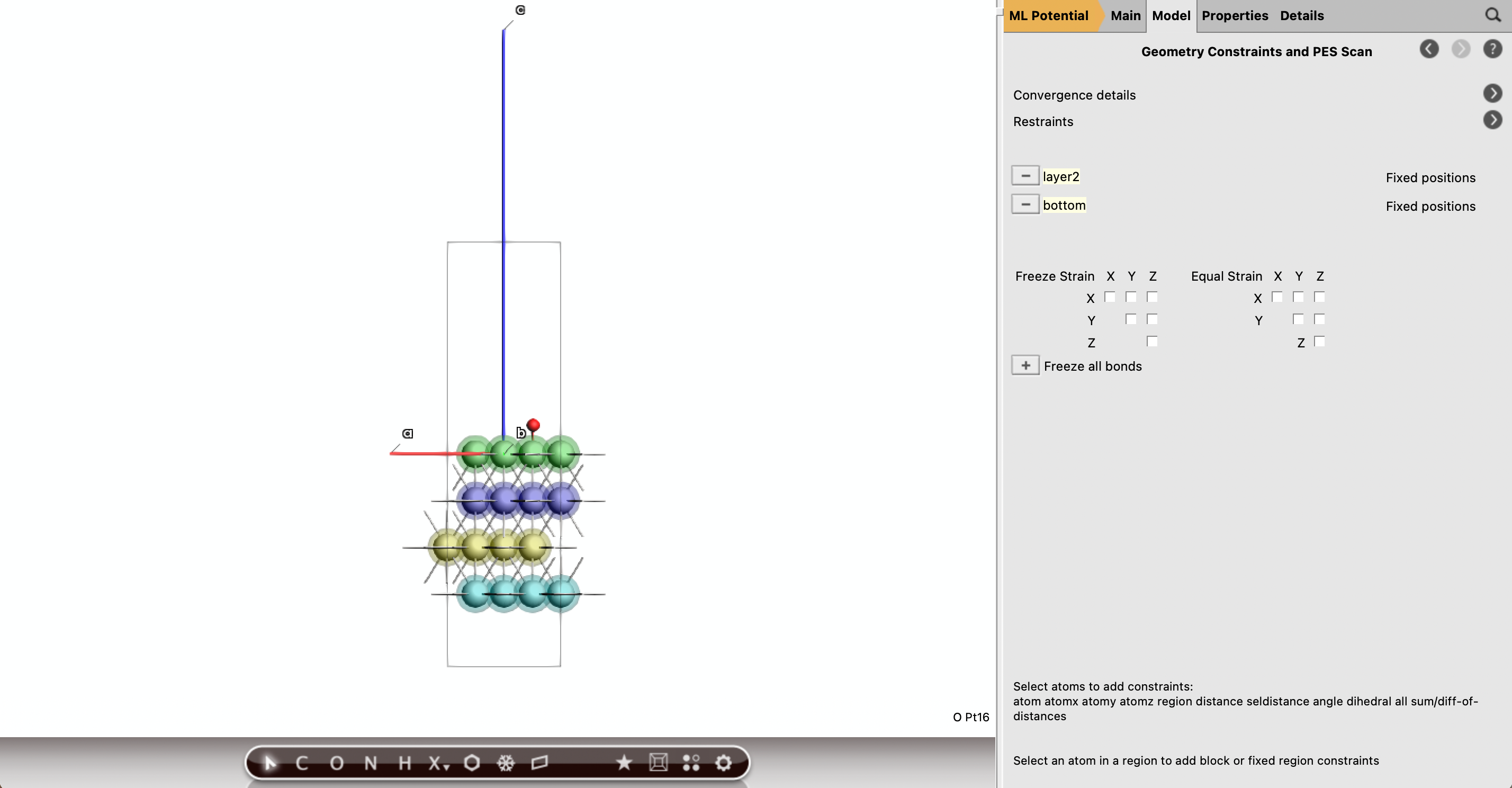
Part E: Freeze the Bottom Two Pt Layers
For the slab-containing geometry optimizations, the notebook freezes the bottom two Pt layers. In the GUI, do the same using atom constraints.
Recommended constraint strategy
Note
Use the same set of frozen Pt atoms for:
the clean slab,
all single-adsorbate jobs,
all O2 jobs, and
both coadsorption jobs.
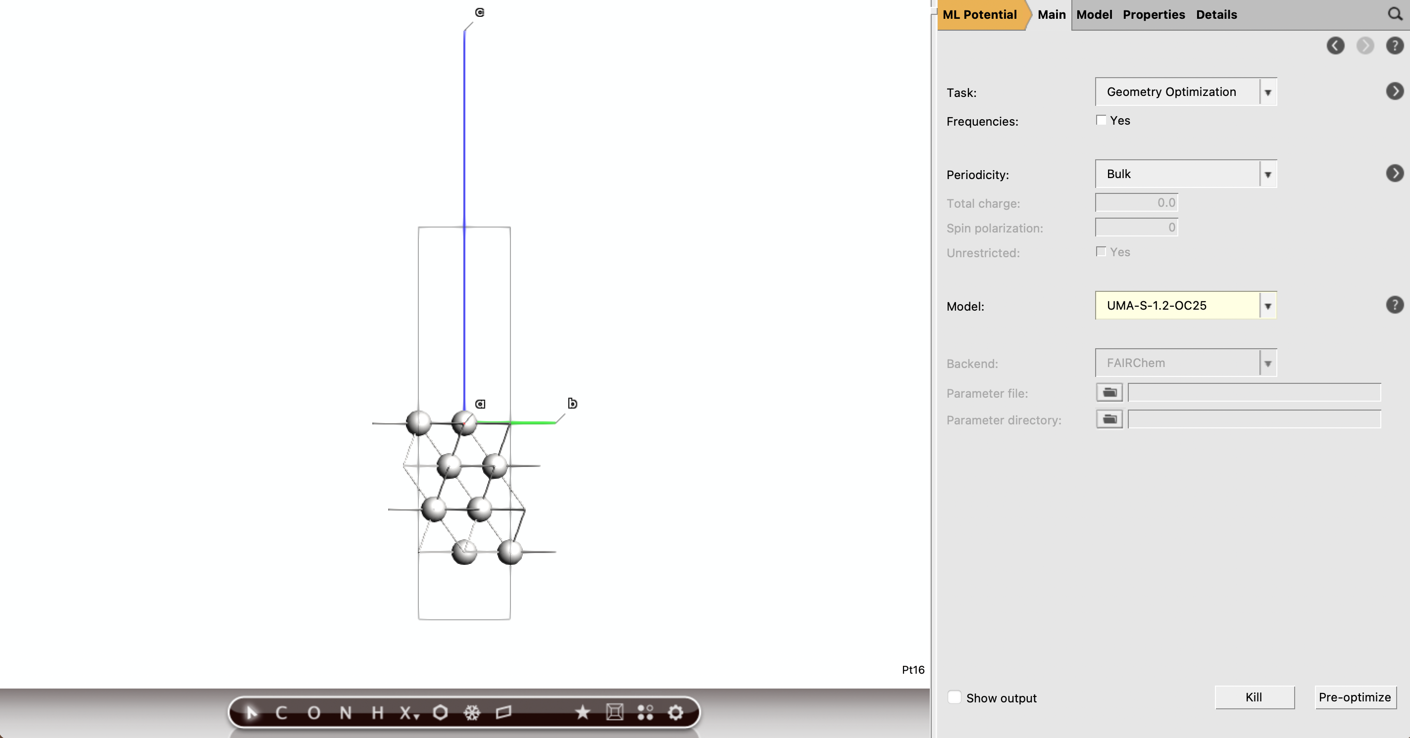
Part F: Run the Geometry Optimizations
You will now relax:
the clean slab,
the gas-phase references
O2,CO, andCO2,all adsorption structures, and
both coadsorption structures.
Warning
For all geometry optimizations, be sure that Optimize lattice is unckecked in Details → Geometry Optimization. We want to use the bulk optimized lattice parameter for all calculations which is that we have used to build the initial Pt(111) slab.
Clean slab
ads_sites_pt111_clean_2x2Gas-phase reference molecules
O2, CO, and CO2ads_sites_o2_gas_ref, ads_sites_co_gas_ref, and ads_sites_co2_gas_refAdsorbate and coadsorbate jobs
Part G: Analyze Adsorption and Binding Energies
After the jobs finish, collect:
the total energy of the clean slab,
the total energies of the gas-phase reference molecules,
the total energies of the relaxed adsorbate structures, and
a few structural metrics such as O-O distance and C height above the surface.
Suggested analysis workflow
ads_sites_pt111_clean_2x2 and record the total energyO2, CO, and CO2You can then evaluate the same binding-energy expressions:
and similarly for O and O2 references.
We report below the calculated binding energies together with those calculated in Ref. [1]:.
Structure |
Calculated binding energy (eV) |
Ref. [1] (eV) |
|---|---|---|
|
1.468 |
1.65 |
|
1.090 |
– |
|
1.721 |
1.58 |
|
1.732 |
– |
|
1.462 |
0.68 |
|
1.521 |
0.72 |
|
3.160 |
2.30 |
|
3.284 |
2.36 |
Part H: Choose the Reaction-State Candidates
At this point, compare the two relaxed coadsorbed states:
Pt + CO(top) + O2(t-fcc-b)Pt + CO(top) + O2(t-b-t)
These are the two candidate initial states for the reaction-path calculations.
Recommended inspection
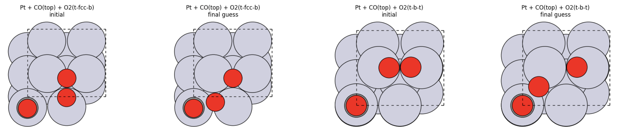
Part I: Build the Final-State Guess for NEB
From the relaxed coadsorbed structure move the oxygen atom from O2 that is second-closest to C to a shorter C-O distance, while keeping the atom ordering unchanged.
Prepare the final structure
1.6 ÅTip
The purpose of this final structure is not to be a fully relaxed product state. It is a consistent endpoint guess that can be used to define a reasonable first NEB path.
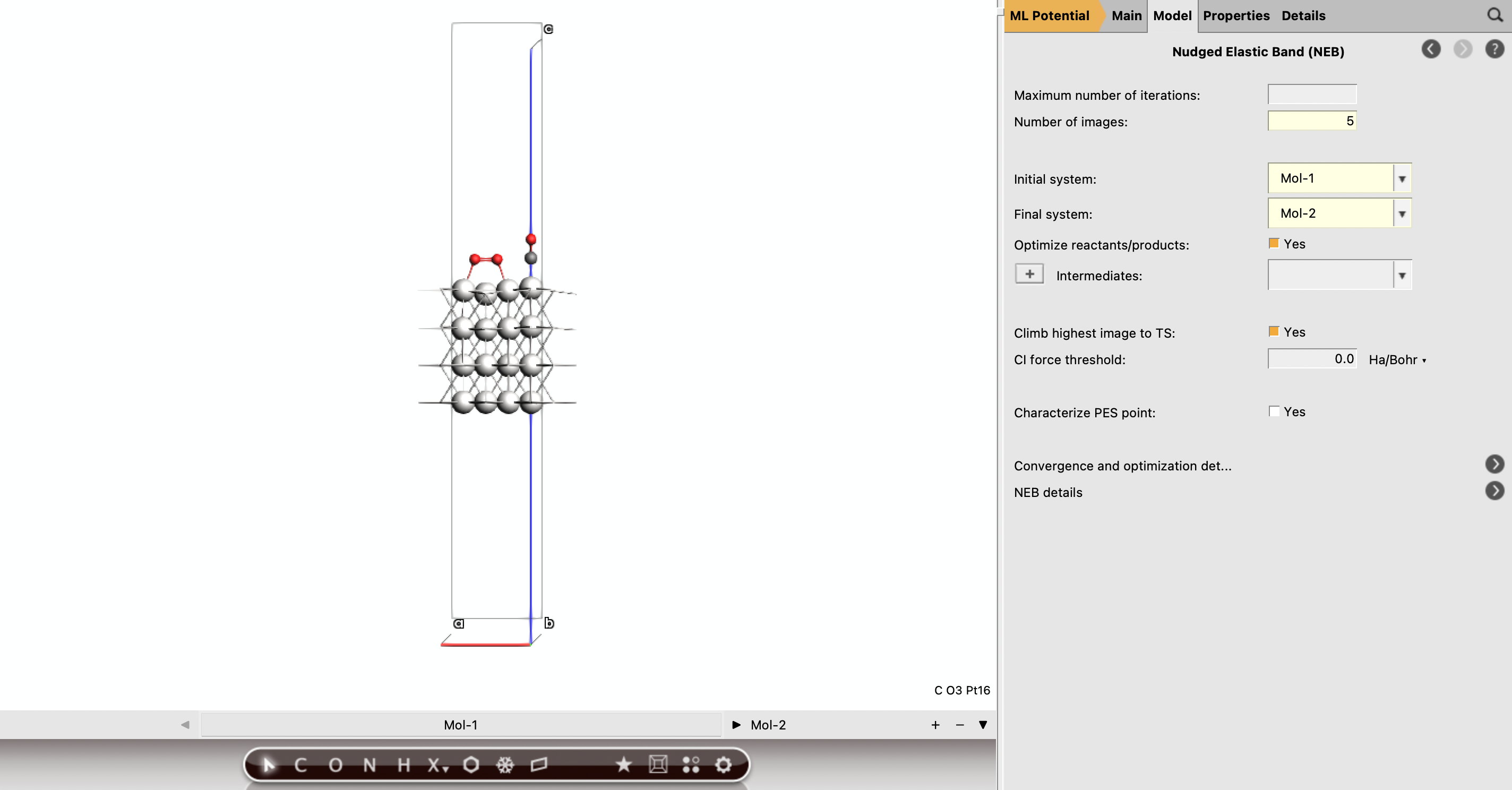
Part J: Run the NEB Calculations
Once you have a reactant structure and a product-side guess with the same atom ordering, you can define the NEB in AMSinput.
Set up the NEB job
Note
Keep the initial and final atom order exactly consistent. This is one of the most important practical requirements for a successful NEB setup.
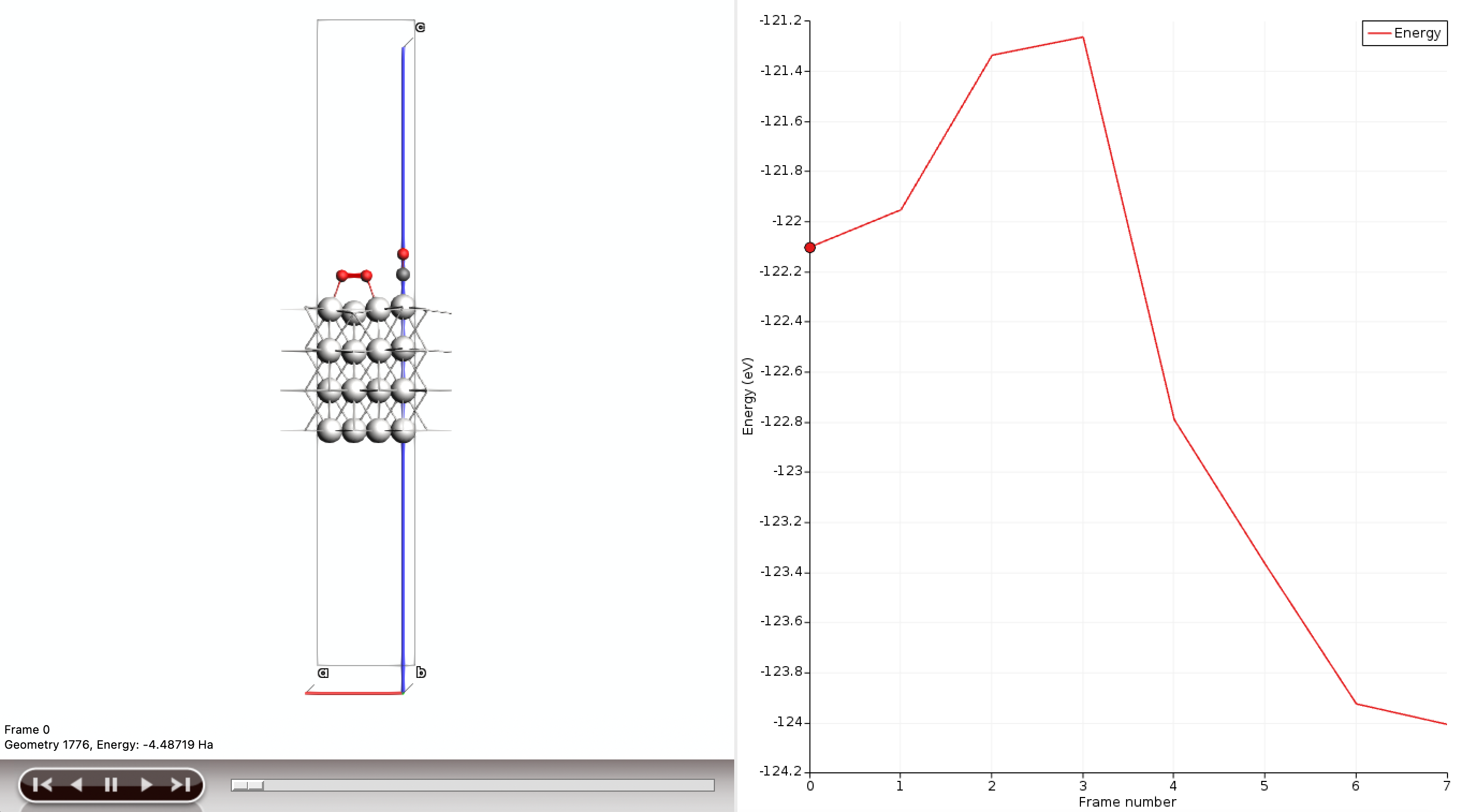
Part K: Inspect the NEB Paths
After the NEB jobs finish, extract and compare the energy profiles.
Suggested analysis workflow
This gives a first reaction-path comparison for the two CO* + O2* motifs. If needed, you can refine the study by:
improving the final-state guess,
increasing the number of images,
enabling climbing-image NEB,
or relaxing the final state separately before rerunning the NEB.