Device Lifetime (Degradation)
Lifetime simulations can be performed to understand the role of degradation processes on the OLED performance.
Note
A pre-made project file is available for this tutorial.
Create Materials
Degradation events involve a change in molecular properties of the layer materials. Create both healthy and degraded variants of the dye molecule.
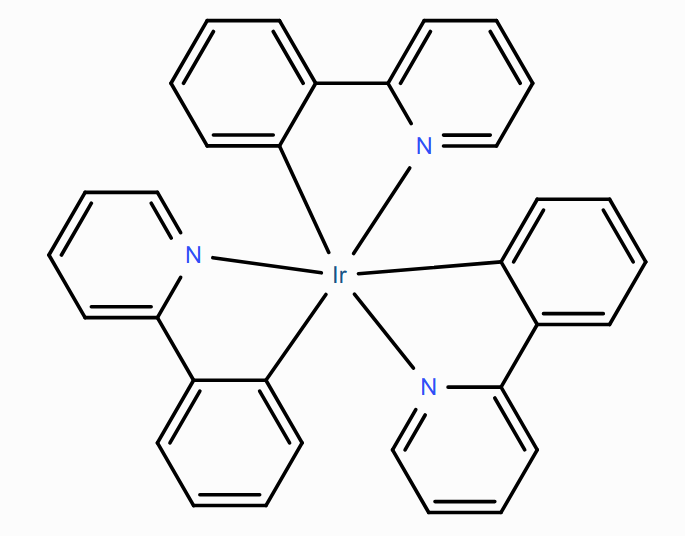
Healthy Phosphorescent Ir(ppy)₃ Dye
Ir(ppy)₃ is used as the phosphorescent dye.
Create a new material with the Phosphorescent Dye template, then set:
Electronic
Energy levels
HOMO = -5.27 eV
LUMO = -1.86 eV
Excitonic
Energy levels
Singlet binding energy = 0.75 eV
Triplet binding energy = 1 eV
Transfer
Dexter prefactor (singlet) = 1
Dexter prefactor (triplet) = 1
Singlet hopping decay length = 0.3 nm
Triplet hopping decay length = 0.3 nm
Photophysics
Intersystem crossing rate = \(10^{10}\,\textrm{s}^{-1}\)
Reverse intersystem crossing rate = \(0\,\textrm{s}^{-1}\)
Triplet radiative decay rate = \(6.1\cdot{}10^{5}\,\textrm{s}^{-1}\)
Triplet non-radiative decay rate = \(1.9\cdot{}10^{4}\,\textrm{s}^{-1}\)
Click the Save Material button at the top.
Degraded Ir(ppy)₃ Dye
The deactivated Ir(ppy)₃ dye molecule loses access to its radiative decay pathway. Create a new Phosphorescent Dye material to store these properties
The radiative decay rate of the triplet excitons is set to 0 following deactivation. The non-radiative decay rate is kept at \(1.9\cdot{}10^{4}\,\textrm{s}^{-1}\).
Create a new material with the Phosphorescent Dye template, then set:
Electronic
Energy levels
HOMO = -5.3 eV
LUMO = -2.25 eV
Excitonic
Energy levels
Singlet binding energy = 0.85 eV
Triplet binding energy = 1.25 eV
Transfer
Dexter prefactor (singlet) = 1
Dexter prefactor (triplet) = 1
Singlet hopping decay length = 0.3 nm
Triplet hopping decay length = 0.3 nm
Photophysics
Intersystem crossing rate = \(10^{10}\,\textrm{s}^{-1}\)
Reverse intersystem crossing rate = \(0\,\textrm{s}^{-1}\)
(!) Triplet radiative decay rate = \(0\,\textrm{s}^{-1}\)
Triplet non-radiative decay rate = \(1.9\cdot{}10^{4}\,\textrm{s}^{-1}\)
Click the Save Material button at the top.
Host: CBP
CBP is used as the host material. Thermalization losses during exciton transport from the dye through the host are included by setting the non-radiative decay rates to \(10^{5}\,\textrm{s}^{-1}\) for singlets and \(10^{4}\,\textrm{s}^{-1}\) for triplets. The radiative decay rates are set to 0.
Create a new material with the Host template, then set:
Electronic
Energy levels
HOMO = -6.08 eV
LUMO = -1.75 eV
Excitonic
Energy levels
Singlet binding energy = 1 eV
Triplet binding energy = 1.7 eV
Transfer
Dexter prefactor (singlet) = 0.95
Dexter prefactor (triplet) = 0.95
Singlet hopping decay length = 0.3 nm
Triplet hopping decay length = 0.3 nm
Photophysics
Singlet fraction for exciton generation = 0.25
Singlet radiative decay rate = \(0\,\textrm{s}^{-1}\)
Singlet non-radiative decay rate = \(10^{5}\,\textrm{s}^{-1}\)
Triplet radiative decay rate = \(0\,\textrm{s}^{-1}\)
Triplet non-radiative decay rate = \(10^{4}\,\textrm{s}^{-1}\)
Click the Save Material button at the top.
Electron Transport Layer: TPBi
TPBi is used as an electron transport layer.
Create a new material with the Transport template, then set:
Electronic
Energy levels
HOMO = -6.2 eV
LUMO = -1.7 eV
Excitonic
Energy levels
Singlet binding energy = 0.75 eV
Triplet binding energy = 1 eV
Transfer
Dexter prefactor (singlet) = 1
Dexter prefactor (triplet) = 1
Singlet hopping decay length = 0.3 nm
Triplet hopping decay length = 0.3 nm
Photophysics
Singlet non-radiative decay rate = \(10^{8}\,\textrm{s}^{-1}\)
Triplet non-radiative decay rate = \(10^{8}\,\textrm{s}^{-1}\)
Click the Save Material button at the top.
Hole Transport Layer: TAPC
TAPC is used as the hole transport layer.
Create a new material with the Transport template, then set:
Electronic
Energy levels
HOMO = -5.5 eV
LUMO = -0.96 eV
Excitonic
Energy levels
Singlet binding energy = 1 eV
Triplet binding energy = 1.59 eV
Transfer
Dexter prefactor (singlet) = 1
Dexter prefactor (triplet) = 1
Singlet hopping decay length = 0.3 nm
Triplet hopping decay length = 0.3 nm
Photophysics
Singlet non-radiative decay rate = \(10^{8}\,\textrm{s}^{-1}\)
Triplet non-radiative decay rate = \(10^{8}\,\textrm{s}^{-1}\)
Click the Save Material button at the top.
Electron Blocking Layer: fac-Ir(pmb)₃
fac-Ir(pmb)₃ is used as an electron blocking layer.
Create a new material with the Advanced template, then set:
Electronic
Energy levels
HOMO = -5.2 eV
LUMO = -1 eV
Excitonic
Energy levels
Singlet binding energy = 0.8 eV
Triplet binding energy = 1.4 eV
Transfer
Dexter prefactor (singlet) = 0.9
Dexter prefactor (triplet) = 0.9
Singlet hopping decay length = 0.3 nm
Triplet hopping decay length = 0.3 nm
Photophysics
Singlet radiative decay rate = \(0\,\textrm{s}^{-1}\)
Singlet non-radiative decay rate = \(0\,\textrm{s}^{-1}\)
Triplet radiative decay rate = \(3.4\cdot{}10^{5}\,\textrm{s}^{-1}\)
Triplet non-radiative decay rate = \(5.7\cdot{}10^{5}\,\textrm{s}^{-1}\)
Click the Save Material button at the top.
Create Compositions
Create a host-guest system for the emission layer.
Set the fraction of the CBP host material to 0.9
Set the fraction of the Ir(ppy)3 dye to 0.1
Add the degraded Ir(ppy)3 material with a fraction of 0 to make it accessible for degradation simulations
Click the Save New Composition button at the top.
Create a Stack
Stack Layers
On the ‘Stack’ page, add the different OLED layers to the device.
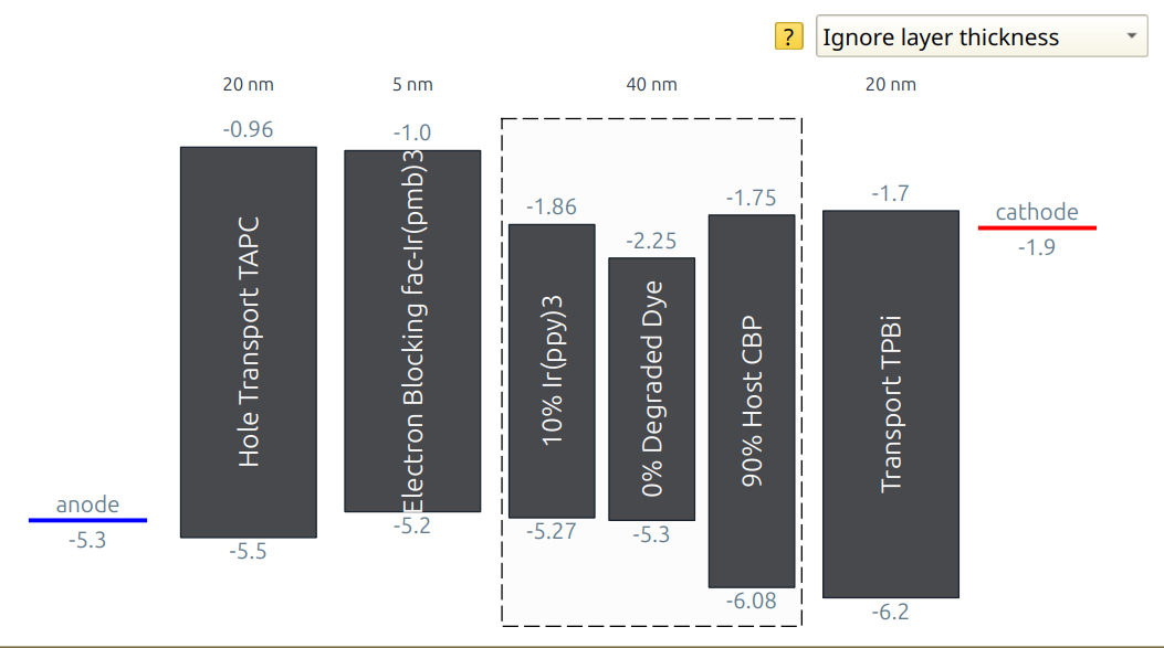
Hole transport layer (HTL): 20 nm of TAPC
Electron blocking layer (EBL): 5 nm of fac-Ir(pmb)3
Emissive layer (EML): 40 nm of the CBP/Ir(ppy)3 composite
Electron transport layer (ETL): 20 nm of TPBi
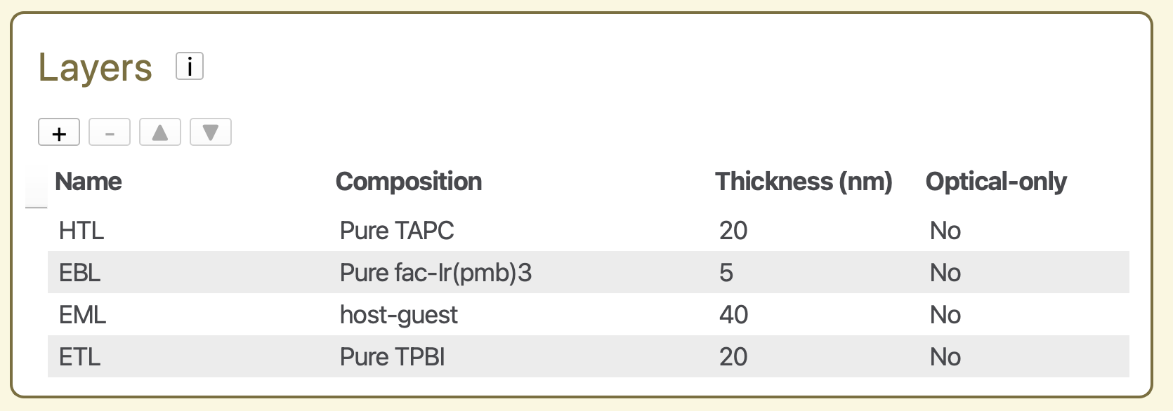
Fig. 75 Layers configuration of the OLED device
Förster interactions
After adding the layers, go to the Förster interactions table and click the Add default interactions button to include the relevant excitonic processes.
Degradation processes
In the Degradation processes table of the stack editor, specify the excitonic events that can trigger degradation of the materials.
Add the following degradation processes with the  button:
Cause: Exciton annihilation
Layer = EML,
Material = Ir(ppy)3,
Degradation product = degraded Ir(ppy)3,
Probability = 1.0
Cause: Polaron quenching
Layer = EML,
Material = Ir(ppy)3,
Degradation product = degraded Ir(ppy)3,
Probability = 0.8
In this setup, all annihilation events in the Ir(ppy)₃ phase cause degradation, while only 80% of polaron-quenching events do so.
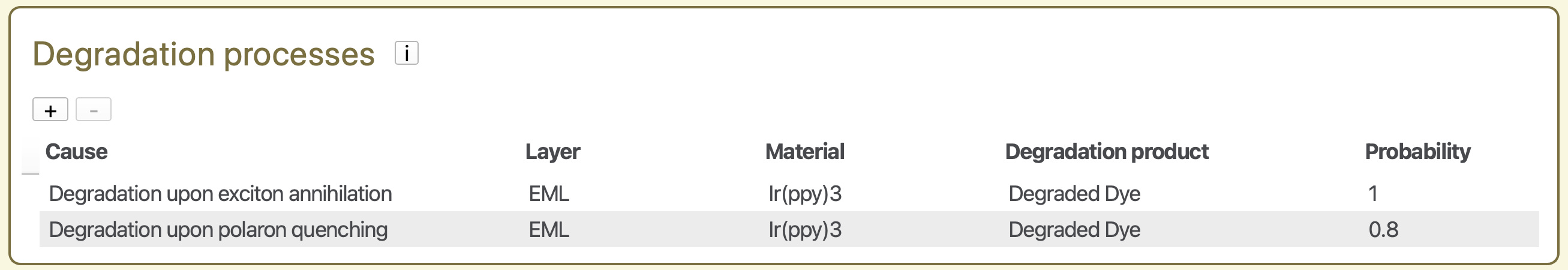
Fig. 76 Degradation processes in the stack editor
Create a Parameter Set
On the Parameters page, use Load preset and select the Lifetime simulation template. This configures the simulation to include degradation events and enables the Degradation option in the Modules tab.
Only one setting needs to be changed manually: Main → Physical Parameters → Device voltage = 6 V.
Leave all remaining parameter settings at their default values.
Starting the Simulation
Set up a new simulation using a single trajectory instance. Then use File → Save and File → Run to start the simulation.
Simulation Output
Monitor the progress of the simulation using BBresults (SCM → BBresults). Device degradation statistics are found in the Sweep → Degradation section.
The number of degraded dye molecules (Sweep → Degradation → Overview → Degradation Events) increases as the simulation progresses.
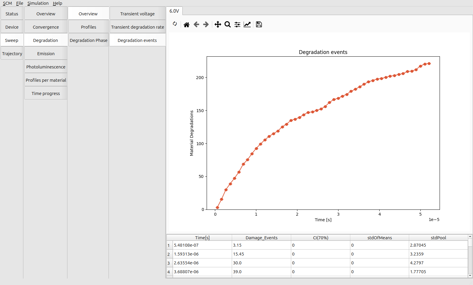
Fig. 77 Number of degradation events at 6 V
The exponential decay in the number of degradation events is mirrored by the decline in the average degradation rate (Sweep → Degradation → Overview → Transient Degradation Rate) as the available number of active dye molecules decreases.
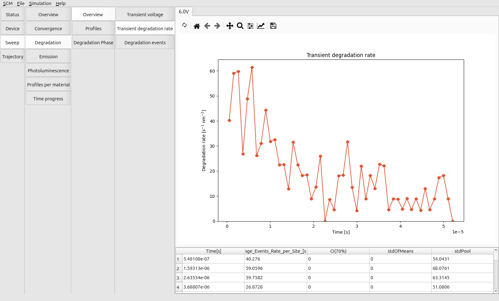
Fig. 78 Transient degradation rate at 6 V
Inspect the distribution of degradation events across the device in the Sweep → Degradation → Profiles → Degradation Rate tab.
Reminder:
The EBL is at 20-25 nm from the anode
The EML is at 25-65 nm from the anode,
The degradation events localize at the interface between the EBL and the EML, where the exciton density is highest.
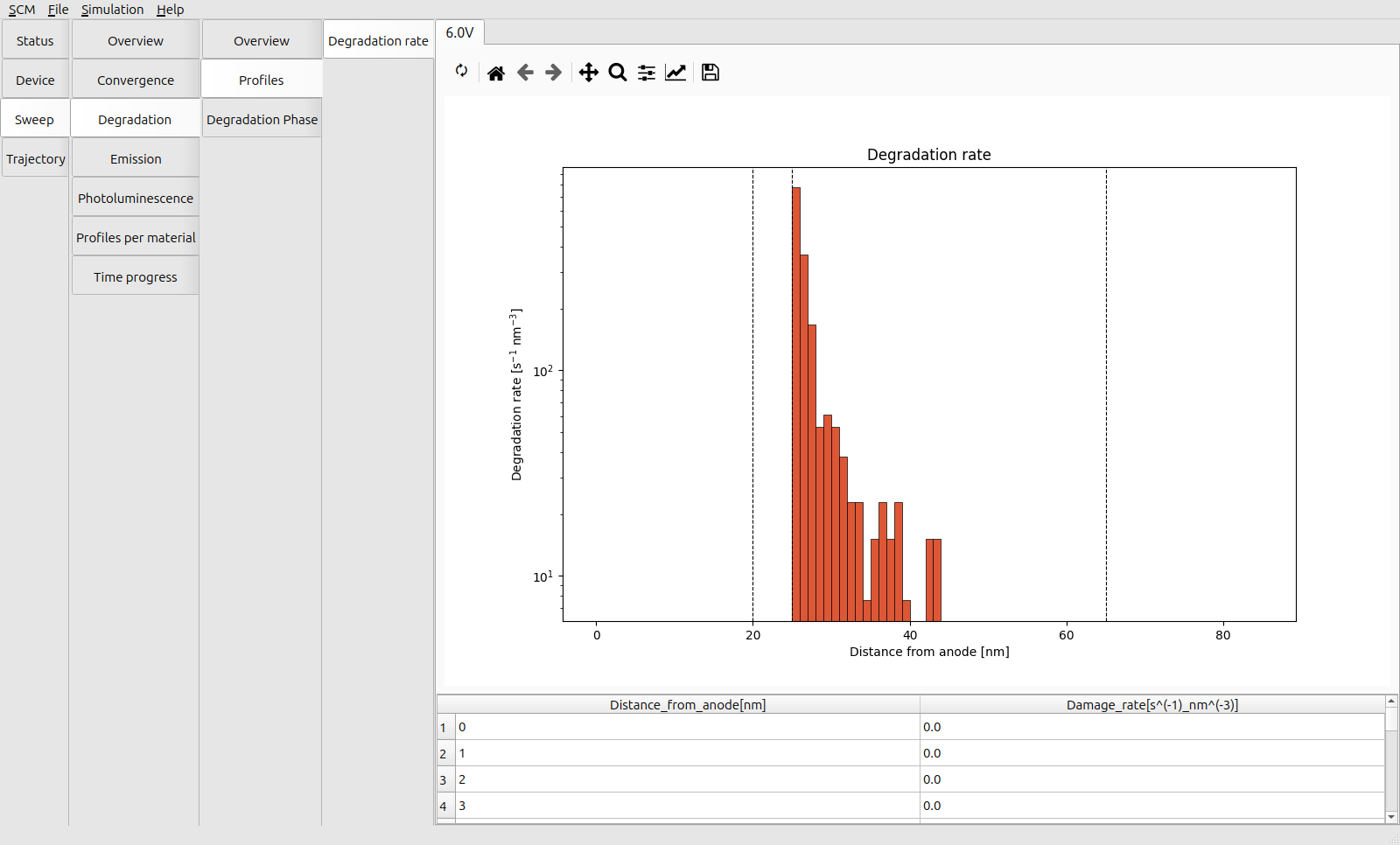
Fig. 79 Distribution of degradation events across the device at 6 V
The dominant degradation mechanism is triplet-polaron quenching (TPQ), as seen by comparing the Sweep → Profiles per Material → Rates → Quenching and Annihilation profiles. This is attributed to the high density of polarons compared to the exciton density required for triplet-triplet annihilation (TTA).
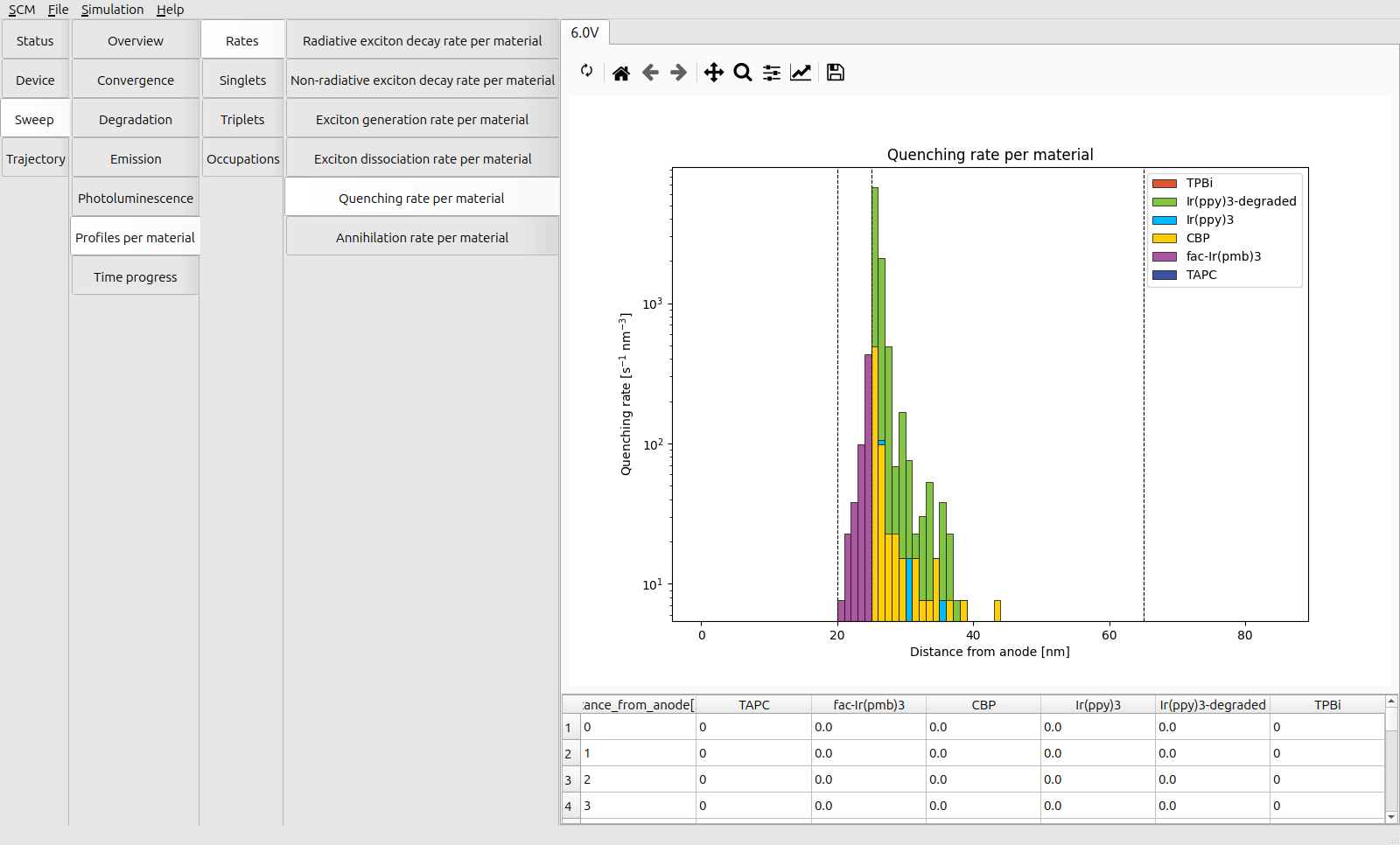
Fig. 80 Distribution of quenching events across the device at 6 V
After degradation, TPQ processes continue to occur for triplets that are formed on the degraded dye molecules. This lowers the efficiency of the device as degradation advances.
The emission rate (Sweep → Degradation → Degradation Phase → Transient Radiative Decay Rate) reduces exponentially, roughly in line with the rate of degradation.
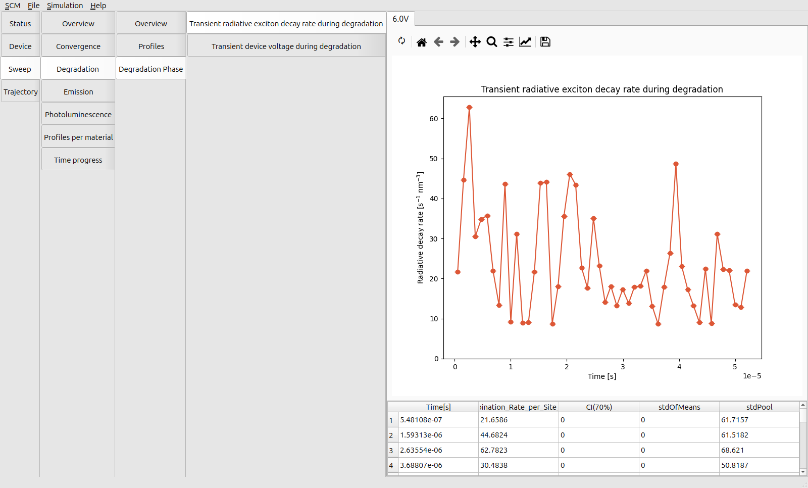
Fig. 81 Transient emission rate at 6 V
The quenching processes reduce the efficiency of the device, but also limit the rate of degradation by reducing the exciton density inside the device, resulting in an extended lifetime. (At the cost of a low luminosity.)
Finally, inspect the molecular distribution in the device after degradation processes have occurred. In Trajectory → Morphology → Device → Volume Fractions, the degraded material shows a localized build-up at the EML-EBL interface.
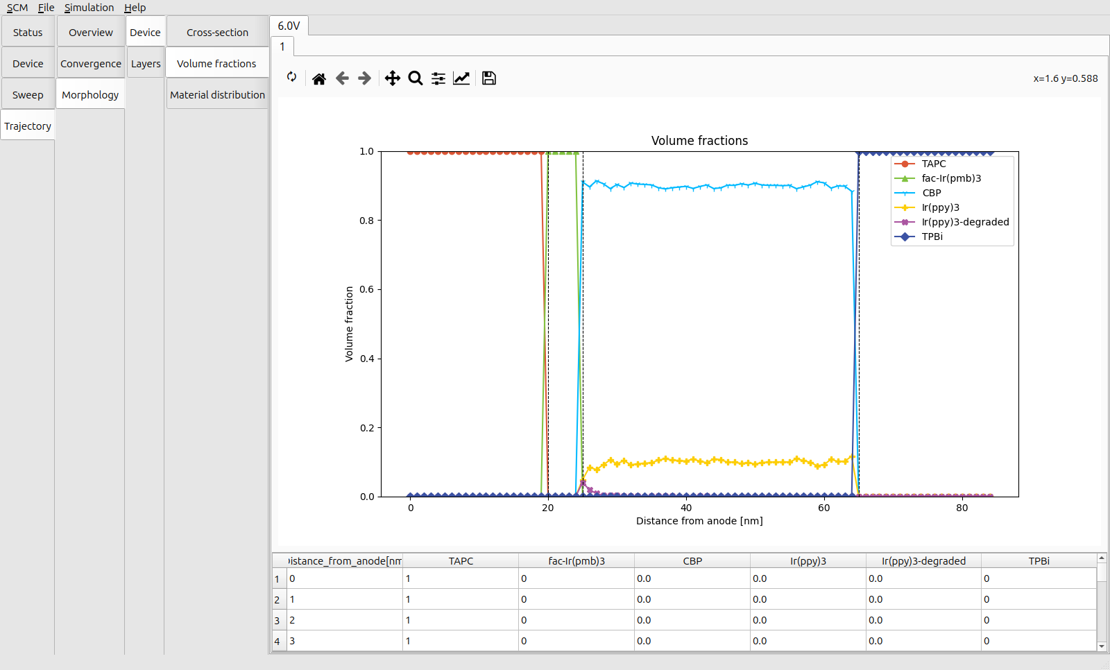
Fig. 82 Material distribution after operating for 100 microseconds at 6 V
The Trajectory → Morphology → Device → Cross-section view can also be used to visualize the exact distribution of materials inside the stack.
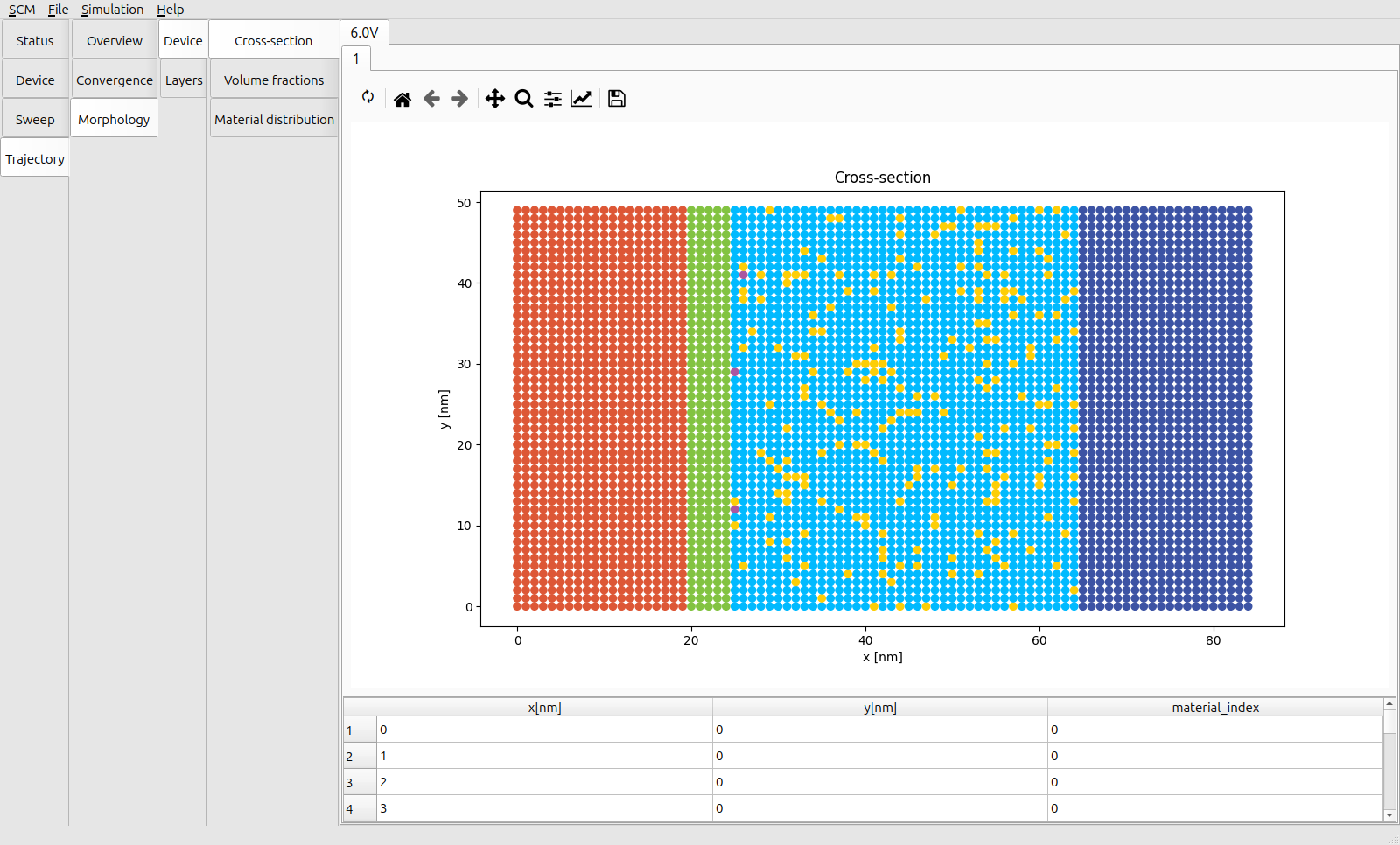
Fig. 83 Layer cross-section of the device after operating for 100 microseconds at 6 V
Tip
Increasing the number of trajectories helps denoise the transient profiles. Particularly for slower processes (such as radiative decay), this reduces the sensitivity to rare events. It also accounts for variations in the distribution of materials and material parameters inside the layers.
An illustration is provided as part of the bulk simulation tutorial.