Basic Usage
This tutorial will showcase the basic features of the graphical user interface for Bumblebee.
BBinput
After starting AMS, you can access the BBinput module from the main SCM menu shown in the top left of the window. You will be greeted with the project overview screen:
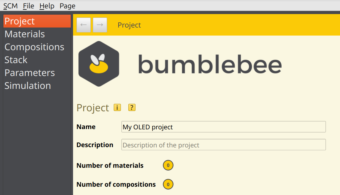
Project Files
Bumblebee simulations are stored in a project file (indicated by the .bee extension). Projects allow you to access the different components needed to run a Bumblebee simulation:
Materials used in the device
Compositions of materials, such as host-guest blends
The stack design
A parameter set detailing simulation conditions
Simulation settings
BBinput opens a new, empty project by default.
Tip
BBinput can also be used to open Bumblebee input files (params.yml) directly.
Note
Older versions of Bumblebee used a web client to manage projects. These files can be exported as YAML files, which can then be loaded by BBinput.
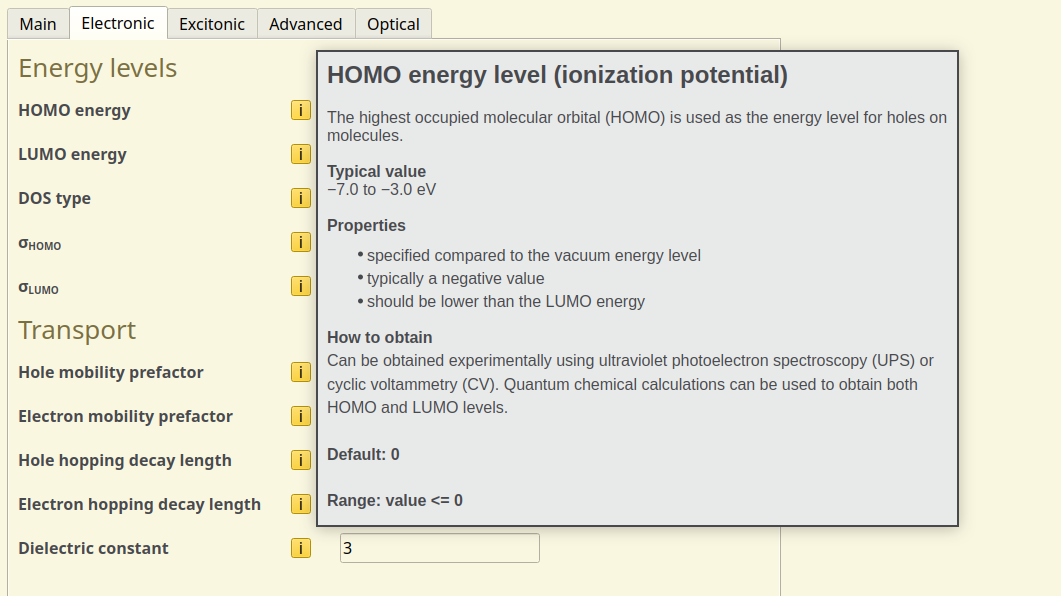
Tooltips
BBinput includes descriptions of the input parameters, including recommended settings. Use the help icons to view these tooltips:
Materials Database
When creating a new device, one typically starts by creating the materials and specifying their parameters. Alternatively, a materials database is also available in BBinput to provide access to commonly used and commercially available OLED molecules.
The material database can be accessed from File → Import → Material:
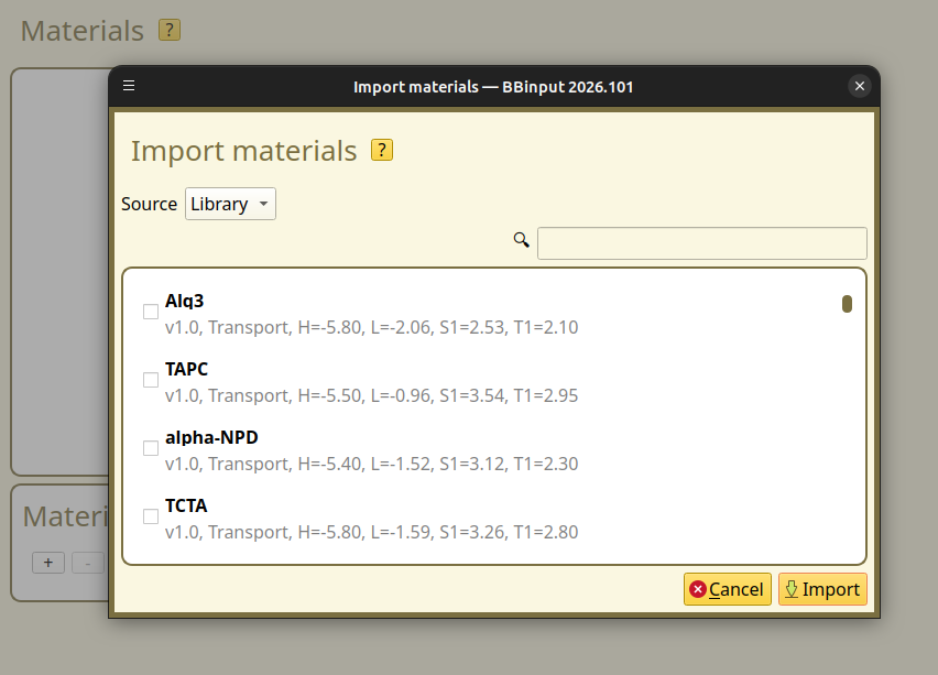
You can also use the import menu to load materials from other project files. Simply change the Source option to File and select the project that you want to import from.
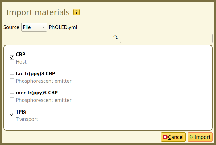
Multiple materials can be imported at once. This allows you to quickly set up a new stack using the same materials that have been used previously.
Bumblebee Workflow
BBinput uses a bottom-up approach when setting up a simulation:
Start by importing or creating the materials
Pure compositions will be created automatically. Mixed layers or special morphologies can be created if needed
Design the stack by adding layers to the device using the available compositions
Once the stack has been designed, the simulation conditions are configured:
The parameter settings determine the simulation type, the external device parameters (such as the voltage) and the active processes
The simulation settings are used to set up parameter sweeps and parallel trajectories
Each of these steps has been given its own page in BBinput, to help keep the parameters organized. The following tutorials will explain in more detail how to use the editors for setting up simulations of typical OLED devices.
Tip
You can use the navigation buttons at the top of the page to move between recently visited tabs.

BBresults
Once a simulation has started, the results can be monitored using BBresults.
The main page of BBresults will show an overview of the running trajectories and the status of ongoing parameter sweeps. The convergence of the simulation is measured by looking at the changes in the device current.
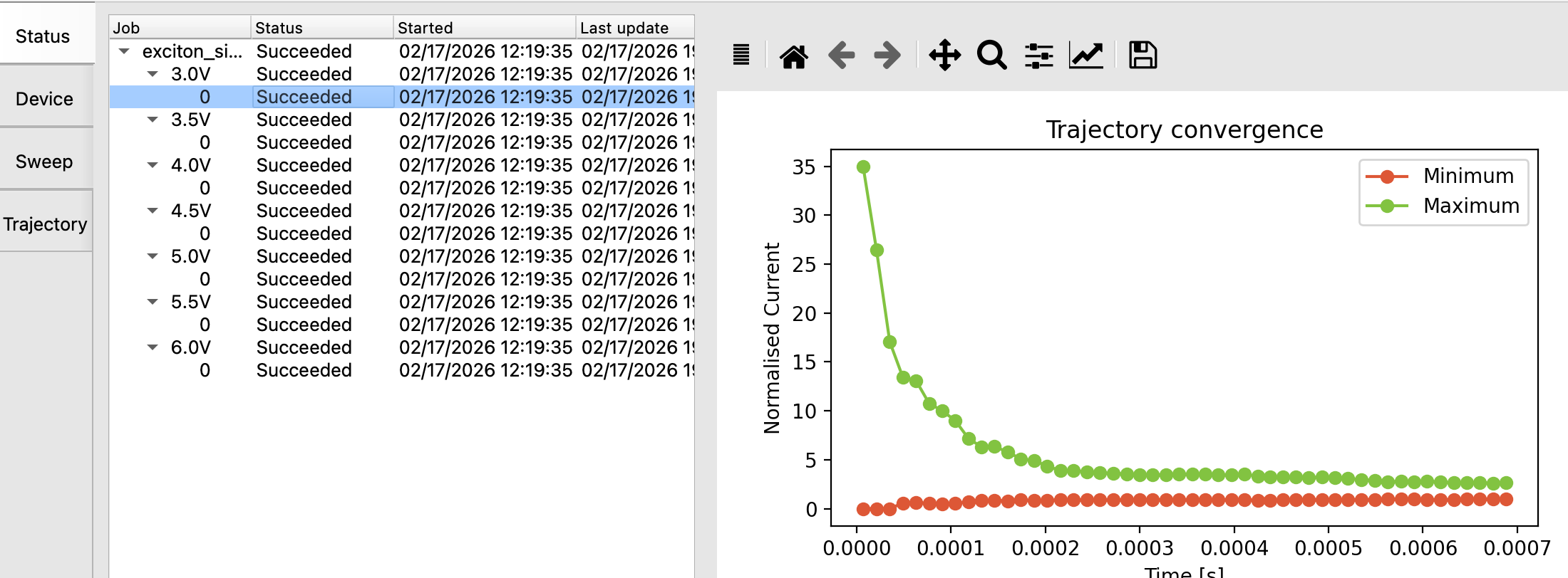
Fig. 3 Bumblebee compares the measured current at every point along the length of the device. A trajectory has reached steady-state once the two lines meet, at which point the current density is constant over the device.
The convergence of a simulation is typically dependent on the voltage. (Where higher voltages typically result in faster equilibration of the charge density.)
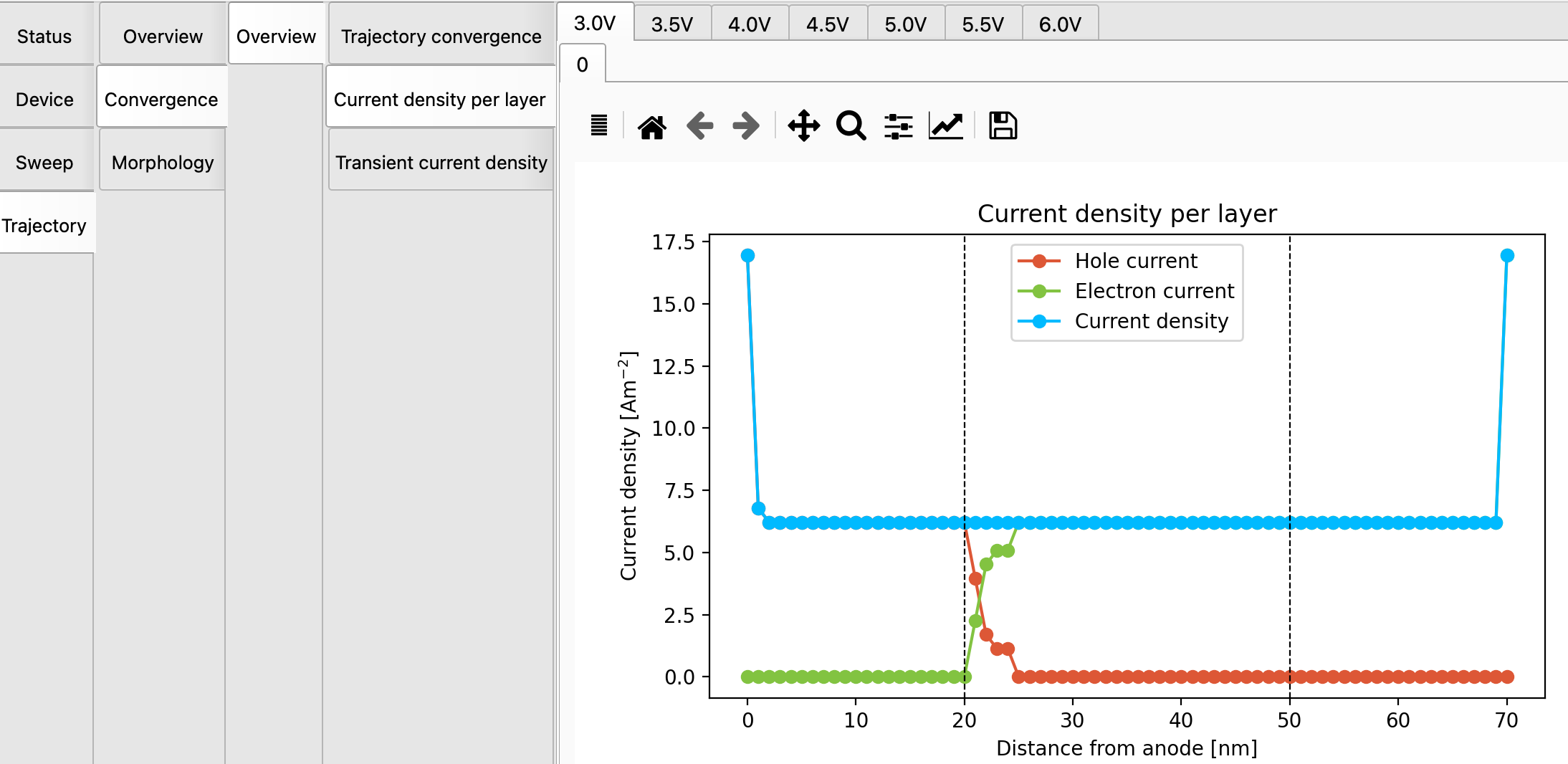
Fig. 4 The trajectory at 3V is still far from convergence
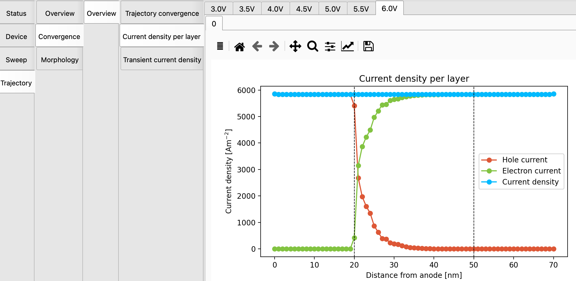
Fig. 5 The trajectory at 6V is nearly at steady-state
The Device, Sweep and Trajectory panels in BBresults provide visualization and analysis of the simulation output. These will be discussed in more detail in the following tutorials.
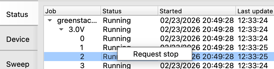
Stopping a Simulation
It may be desirable to stop a simulation before it has reached the maximum number of steps:
A high-voltage trajectory may have converged early
The statistics / error estimates have reached the desired accuracy
You want to terminate the simulation to free up computational resources
You can select trajectories or sweep points from the main Status menu in BBresults. Right-click and Request stop to wrap up these simulations (while others may keep running). Alternatively, you can access this option from the Simulation → Request stop menu.
Tip
You can set convergence criteria in the Output tab in the Parameters page of BBinput. Bumblebee will then automatically stop any simulation that has reached steady-state.
It may however be desirable to continue running the simulation for a period of time once convergence has reached, to improve the statistics and reduce the error bars shown in the reports.
Stopped simulations can be restarted by using the Simulation → Extend trajectories option. This option can be used to improve device statistics by requesting additional samples. Additional trajectories or sweep points can also be added to a simulation by choosing the Add trajectories and Add sweep points options.
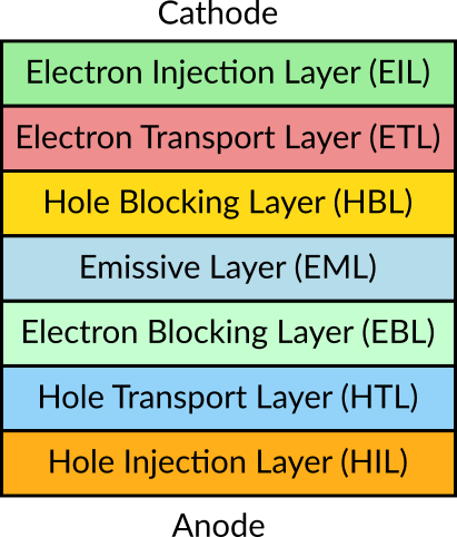
Layer Abbreviations
In these tutorials, abbreviations will frequently be used to reference different layers of the OLED stack. Commonly-used stack elements have been summarized in the figure below: