Transient Switching
Kinetic Monte Carlo simulations can be used to investigate the response of organic electronic devices to external perturbations.
Here, we consider the effect of switching the device illumination on the current produced by an organic photovoltaic (OPV).
Create Compositions
The OPV layer materials were created as part of the photoluminescence tutorial. Here, we will consider the photoresponse of a bulk heterojunction morphology for the OPV.
We create an advanced composition using the PCBM and P3HT components. Select PCBM as the background material. A P3HT linear gradient is used ranging from a 0.8 fraction at the anode to 0.2 at the cathode.
Create a Stack
The OPV stack is created by selecting a 5 nm BCP electron transport layer, a 20 nm P3HT/PCBM donor/acceptor heterojunction layer and a 5 nm PEDOT:PSS hole transport layer.
Enable the default Förster processes to include inter-layer singlet diffusion. We add absorption processes to both P3HT and PCBM materials in the heterojunction layer. We use an absorption probability of 0.8 for both materials to account for optical loss processes.
Create a Parameter Set
We will use the PV template parameter set for the photovoltaic device. This will automatically enable the photoluminescence module.
Device Settings
We set the electrode levels to -4.6 for a silver anode and -4.7 for an ITO cathode contact. The external device voltage will be set to 0.5 V.
In the Photoluminescence tab, we set the starting fluence to 0. Absorption processes are configured to yield singlet excitons.
Transient Switches
Perturbations to the device operation can be added in the Transient Parameters tab.
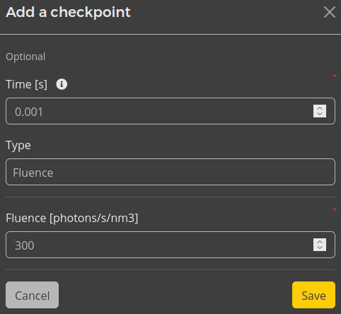
Device perturbations must first be activated by enabling checkpoints. Individual perturbations can then be added to the simulation by selecting the Add checkpoint option.

Fig. 62 Checkpoint editor for configuring transient responses
Checkpoints can be provided for various parameters, such as the voltage, current or fluence. Checkpoints occur at a designated time after the simulation has commenced. Multiple checkpoints of different types can also be combined to replicate complex interactions.
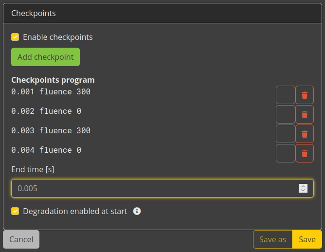
After 0.001 seconds, we will set the fluence to 300 \(\textrm{photons/s/nm}^3\). Light switching is investigated by alternating the fluence every 0.001 seconds.

Fig. 63 Transient configuration for pulsed illumination
An end time of 0.005 seconds is specified in the Transient Parameters tab, after which the simulation concludes. This end time overrides the maximum simulation time defined in the termination criteria.
Running the Simulation
A single disorder instance will be used for this tutorial.
After the simulation has concluded, the transient response of the OPV current to the pulsed illumination can be viewed in the Transient Photoluminescence and Transient OLED Response sections of the Multibox Report.