Concepts and Terminology
LINK bonds
When performing a QM/MM simulation, one often wants to partition the system such that some covalent bonds cross the QM/MM boundary. These so-called ‘link’ bonds demand special attention in any QM/MM implementation. The link bonds are a critical aspect of the QM/MM method used here and a good understanding of the concepts is essential. In this section we describe how they are treated in ADF and we introduce the nomenclature that is used throughout the manual.
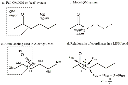
Figure 1-1 Example of QM/MM partitioning and details of the naming conventions adopted in ADF.
Figure 1-1a depicts a simple molecular system that has been divided into QM and MM regions by the dotted polygon. In this example there is only one link bond, or one covalent bond that traverses the QM-MM boundary (that cross the dotted polygon). When a covalent bond traverses the QM-MM boundary, the electronic system of the QM region must in some way be truncated across this bond. Several methods of dealing with this problem have been proposed in the literature. By far the most commonly adopted method, which was originally introduced by Singh and Kollman [6], involves capping the QM system with a ‘dummy atom’ or what we call a ‘capping atom’ (We use capping atom to avoid confusion with the dummy atoms used in ADF). Since the pioneering work of Singh and Kollman [6] many variations of the basic capping atom approach have evolved. In ADF, one of the adopted approaches is the one developed by Maseras and Morokuma which has been given the name the ‘Integrated Molecular Orbital and Molecular Mechanics’ or the IMOMM method by the authors. The key feature of the capping atom approach is that the electronic structure calculation is performed on what is referred to as the ‘QM model’ system where the MM region is removed and replaced with capping dummy atoms (often hydrogen but not necessarily so). Figure 1-1b depicts the QM model system corresponding to the example system presented in Figure 1-1a. The capping atom satisfies the valence requirements of the QM region and allows for a standard electronic structure calculation to be performed on the QM fragment. It is important to realize that the capping atom is not part of the real system, but is simply an atom that is introduced to truncate the electronic system of the QM region. This is why it is often referred to as the dummy atom. For every ‘link’ bond there are three atoms of importance, the capping atom and the two atoms that are part of the ‘real’ link bond - one from the QM region and one from the MM region. Figure 1-1c illustrates the three atoms involved in the link bond. From this point on, we will refer to the MM atom that is part of the ‘real’ link bond as the link atom; it is labeled ‘LI’ in Figure 1-1c. Although both the QM and MM atoms that are part of the link bond could be considered ‘link’ atoms, we designate only the MM atom as the link atom, because it has a special place in the ADF QM/MM input. It is this atom that is replaced by the capping atom in the electronic structure calculation of the QM model system.
Although the capping atom approach is convenient from the standpoint of the electronic structure calculation, the ‘extra’ capping atoms complicates the situation, as they do not exist in the real system, see Figure 1-1c. For each link bond, there are potentially three extra nuclear degrees of freedom (corresponding to the Cartesian coordinates of the capping atom) that are not present in the real system. In the IMOMM/ADF implementation [1] we alleviate the problem by removing the MM atom that is part of the ‘real’ link bond as a free variable. Instead we define its position in terms of the QM atom it is bonded to and the capping atom that replaces it in the QM model system. More specifically, the MM link atom is constrained to lie along the bond vector of the capping atom bond, via the simple relationship expressed in equation 1.1 and depicted in Figure 1-1d. Here, XMM , Xcap and XQM refer to the Cartesian coordinates of the subscripted atoms and a is a constant defined as the ratio of the real link bond length to that of the length of the capping bond.
XLI = a Xcap + (1 - a) XQM (1.1)
For each link bond, there is a unique a parameter that is held constant throughout the simulation. Since the capping atom is often at a shorter distance than the real MM atom, alpha is usually greater than unity. For example, when a Hydrogen capping atom is used to cap a C-C single bond, a is around 1.38. Note that the energy depends on the value chosen for this parameter a, and comparisons between two systems are meaningful only when the values for them are chosen equal.
Although the position of the MM atom is not an independent variable (or free degree of freedom), the bond length of the link bond can change during a geometry optimization. If the capping bond in the model QM system stretches or contracts, so does the link bond in the full system. Note that any forces exerted on the LI atom are projected onto the connected QM atom and onto the capping atom. For more details see references [1, 2].
In the AddRemove model [3] the position dependence is reversed. Instead of the real classical LI atom following the artificial capping atom, it is the position of the capping atom that is constrained:
Xcap = XQM + Req ULI-QM (1.2)
Here Req is the equilibrium distance (from the force field !) for the QM-cap bond, while ULI-QM is the unit vector pointing from QM to LI.
This means also that the artificial degrees of freedom of the capping atom are being removed ! Moreover, after every QM geometry optimization cycle, the interactions of the artificial capping atoms with the real QM atoms are corrected for by subtracting the corresponding MM interactions [3]. In this way, the capping atoms are Added and Removed. It has been shown [3] that this choice gives a much better description for the bonds involved in the QM/MM boundary region than the IMOMM/ADF scheme.
The ADF QM/MM Hybrid Potential
This section summarizes how the QM/MM hybrid potential is constructed in the IMOMM and AddRemove methods. A more detailed and formal discussion can be found in references [3] [2, 6]. The two basic components of the QM/MM potential are the potential arising from the electronic structure calculation of the QM model system and the potential arising from the molecular mechanics force field calculation.
In the IMOMM method the potential of the QM model system acts as a base where additional molecular mechanics potentials are added. When there are no covalent bonds that cross the QM/MM boundary the situation is straightforward. For example, consider a QM/MM simulation in which there are two molecules, one in the QM region and the other in the MM region such that no bonds cross the boundary. All MM potentials needed to define the MM molecule are included. Additionally, all non-bonded MM potentials between QM and MM atoms are included. All bonded MM potentials within the QM molecule are discarded because they are accounted for by the QM calculation.
When there are covalent bonds that cross the QM/MM boundary, the question of which MM potentials to accept and which to discard is not so easy to answer. Consider the system shown in Figure 1-2a, with one covalent bond that traverses the QM/MM boundary. Shown in Figure 1-2b is the equivalent QM model system with a capping hydrogen atom. In the IMOMM approach, MM potentials are only included if they depend on atoms that have no equivalent in the QM model system. Hence, any MM potential in which all atoms involved are QM atoms are NOT included in the total QM/MM potential, for instance the C2 -C1 bond stretching or the C2 -N3 -H4 angle bending potentials. Furthermore, the C5 -N3 bond stretching potential is also not included, because an equivalent in the QM model system exists, namely the N3 -Hcap bond. The QM potential is assumed to adequately model the link bond. The same is true for the C2 -N3 -C5 bending potential. Again there is an equivalent in the QM model system that involves the capping hydrogen atom. The rule therefore also implies that any MM potentials in which only QM or LI atoms are involved, are NOT included in the hybrid QM/MM potential. On the other hand, all MM potentials that involve at least one or more MM atoms are included. For example, C2 -N3 -C5 -O6 torsion potential is included because there is no equivalent in the QM model system and the O6 atom is a pure MM atom.
There is only one exception. It involves the non-bonded interactions between QM atoms and LI atoms. From the rules above this MM potential should be discarded. However, in the IMOMM method this potential is included. The reasoning is that this interaction in the real system is not adequately modeled in the QM model system.
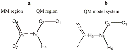
Figure 1-2 a) QM/MM partitioning. b) The equivalent QM model system. The numeric subscripts simply refer to the atom numbering.
In the AddRemove model [3], things are less complicated. The classical LI atom is treated as a normal MM atom with corresponding MM potentials to both the MM and QM atoms. The same goes for the MM correction potentials of the capping atoms (only with the real QM atoms and other capping atoms). For the AddRemove model, it’s best to view the setup as the setup of two systems, one with all real QM and MM atoms (case a) and one with the real QM atoms and the capping atoms (case b). For both you need to build up the force field; in the former case (a), all interactions involving only QM atoms are ignored (these are already present through the QM calculation), while in the latter case (b) all interactions without contributions from the capping atoms are ignored. The interactions of case (a) are the normal MM/MM and QM/MM interactions, while the interactions of case (b) are used for correcting the QM interactions of the capping atoms. This also means that an atomic force field type should be assigned to the capping atoms, which is being handled in the LINK_BONDS block.
Nomenclature and Terminology
This section summarizes the naming conventions that are used throughout this document. Some of the terminology has already been described in the previous section. Since the nomenclature describing the link bonds can be somewhat confusing we recommend that special attention be given to this section.
Full QM/MM system vs. QM model system
When performing a combined QM/MM simulation, the molecular system is divided into QM and MM regions as shown in Figure 1-1a. We will refer to the total hybrid system as the ‘full system’ or sometimes we will refer to it as the ‘real system’. The ‘QM model system’ is the capped system for which the electronic structure calculation is performed. Figure 1-1a shows the full system and Figure 1-1b depicts the corresponding QM model system.
Link bonds and capping atoms
The ‘link bonds’ are those covalent bonds that cross the QM-MM boundary in the full QM/MM system. A link bond involves one atom that belongs to the MM region and one from the QM region, see Figure 1-1a. The ‘capping atoms’ (sometimes termed dummy atoms) refer to the atoms that are used to cap the valence in the model QM system. Capping atoms are not part of the full system. The ‘capping bond’ is the covalent bond in the QM model system that corresponds to the link bond in the real system. The terms capping atom or capping bond only refer to the model QM system, whereas the term LINK only refers to bonds or atoms in the real system.
QM, MM and LI atom types
In the ADF QM/MM input, each atom in the full system must be designated as a QM, MM or LI atom, where LI refers to link. Figure 1-1c shows these designations for the example system. Although two atoms are involved in a LINK bond, we only designate the atom in the MM region as the LI atom. We do so because this atom corresponds to a capping atom in the QM model system. In systems where there are no covalent bonds that cross the QM/MM boundary, there will be no LI atoms.
Atom types
There are several different meanings of the term atom and atom type that have arisen because of the hybrid nature of the QM/MM method, see the following items.
QM/MM type or QM/MM atom type (MM, QM or LI)
Refers to the partitioning of the full system into QM and MM regions. As described above, there are only three QM/MM types allowed: QM, MM, and LI. Each atom in the full system is assigned a QM/MM atom type in the MM_CONNECTION_TABLE subkey block.
Force Field atom type
The atom type used in the force field calculation. Each atom in the full system is assigned a force field atom type in the MM_CONNECTION_TABLE subkey block of the input. Force field atom types assigned to each atom must correspond to atom types defined in the Force field file. Force field atom types must be assigned to all atoms, even the QM atoms because the non-bonded interactions between QM and MM atoms are treated by a molecular mechanics potential.
ADF atoms or ADF fragments
The atom types used for the electronic structure calculation of the model system. These are the atoms or fragments defined in the FRAGMENTS key block in a standard ADF calculation. The ADF fragment types used for the capping atoms are defined in the LINK_BONDS subkey block. Note that capping atoms can only be single atom fragments, not compound fragments as allowed by ADF.
Partitioning into QM and MM regions
In a QM/MM simulation the basic question is how to partition the system into QM and MM regions. When studying an active site of a catalyst, for example, one must decide where to put the QM/MM boundary. Putting the boundary too close to the reaction center will question the chemical realism of the model. On the other hand, if one makes the boundary too far away, the computational expense of the QM calculation may become problematic. Each system is different in this respect and the user must make the proper tests to validate the appropriateness of the QM/MM partitioning used. We strongly suggest that the reader examines the literature on QM/MM methods and understands the basic limitations of the approach.
Below we give examples of QM/MM partitioning that should not or can not be used. For comparison, we also give some representative examples of QM/MM partitioning that the program does allow. In the examples, the region enclosed in the dotted polygon represents the QM region and the atoms labeled with ‘LI’ are the so-called Link atoms.
First, the QM/MM boundary should not cut across double, triple or aromatic bonds as shown in Figure 1-3. In these examples, a simple capping atom does not satisfy the valence of the QM fragment and the electronic structure of the QM model system would be drastically different from that of the ‘real’ system.

Figure 1-3 Examples of partitioning that should not be used because the link bonds are double or aromatic bonds.
Next, figure 1-4a depicts examples of partitioning that are not allowed because the LI atom has a covalent bond to more than one QM atom. A LI atom can only be bonded to one QM atom. Figure 1-4b shows the opposite, which is allowed. In other words, one QM atom can be bonded to more than one LI atom. This is due to the partitioning scheme that was used and the geometric relationship expressed in Equation 1.1, which restricts the position of the link atom, based on the QM and dummy atom. Note that there is no limit to the number of LI atoms or link bonds, just that each LI atom can only be bonded to one QM atom.

Figure 1-4 a) Examples of partitioning that are not allowed because the LI atom has a covalent bond to more than one QM atom. b) The allowed reverse of the examples showed in (a). A LI atom can only bond to one QM atom.
Then, figure 1-5 provides some representative examples of partitioning that the program does allow. Example a shows a typical solute-solvent QM/MM partitioning where there are no link bonds at all. Example b depicts two separate molecules each possessing a QM and a MM region. We emphasize that any number of molecules and link bonds can be used. Recall that in the IMOMM/ADF method all link bonds have a different a parameter associated with them, each specified by the user, upon which the energy depends (and which are difficult to choose or generalize). In example b there would be four independent a parameters. Example c seems very similar to the earlier example in Figure 1-3. The difference is that the ring in Figure 1-cd is not aromatic and consequently the link bonds in example d cross single bonds. Example d shows a single molecule, with two QM regions separated a MM region. For this example, two equivalent pedagogic representations of the sample partitioning are displayed. Example e is a complex organometallic system that we have tested the QM/MM approach on.

Figure 1-5 Representative examples of QM/MM partitioning that can be used in ADF QM/MM ADF.