Nudged Elastic Band (NEB)
The Nudged Elastic Band (NEB) method [1] can be used to find a reaction path and the transition state between a reactant and a product state.
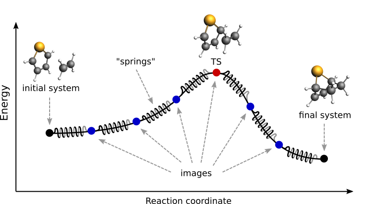
Fig. 1 Pictorial representation of a reaction path computed with NEB
At the beginning of a NEB calculation, the geometry of the initial and final systems are optimized to minimize their energy (unless the OptimizeEnds option is set to False).
Then, a rough approximation of the reaction path is build: a set of images is created by performing a linear interpolation between the initial and final systems. Optionally, an intermediate system can be provided, in which case the interpolation is performed between the initial and intermediate systems, and then between the intermediate and final systems.
Finally, a reaction path is found by performing a simultaneous optimization of all the images. In the NEB method the images are not independent from each other. The force on each image depend on its neighboring images: at each step the forces parallel to the reaction path are eliminated and a so-called spring force is added that tries to keep each image in the middle between its neighbors. This does not let images slide to the initial or final reaction state and ensures that they are evenly distributed along the reaction path.
During the NEB path optimization, a climbing image algorithm is used to drive the highest-energy image in the path to the transition state (unless the Climbing option is set to False).
Be aware that NEB is a computationally expensive method, typically involving hundreds if not thousands of energy and gradients evaluations.
Input
A NEB calculation in AMS is triggered by setting the Task to NEB:
Task NEB
The NEB method requires two or three input systems. The first, unnamed system is used as the initial system and the system called final is used as a final system. These two systems are mandatory. This is an example of system-definitions for a HCN isomerization reaction:
Task NEB

# This is the initial system:
System
   Atoms
      C   0.0000   0.0000   0.0000
      N   1.1800   0.0000   0.0000
      H   2.1960   0.0000   0.0000
   End
End

# This is the final system (note the header 'final' in the next line):
System final
   Atoms
      C   0.0000   0.0000   0.0000
      N   1.1630   0.0000   0.0000
      H  -1.0780   0.0000   0.0000
   End
End
Optionally, a third system, called intermediate, can be used to provide a better approximation for the transition state. The intermediate system will be placed in the middle of the chain. When providing three input systems it may be a good idea to optimize the ends in advance and set OptimizeEnds to False to prevent creating an unbalanced reaction path.
Note that not only the atomic coordinates, but also the lattice parameters and the charge (if non-zero) must be set for all input systems.
Important
The order in which atoms are specified in the System%Atoms blocks must be the same for the initial and final systems (if you provide an intermediate system, you must use a consistent atom-ordering for that too). The order of the atoms must be consistent because the images-interpolation algorithm maps the n-th atom of the initial system to the n-th atom of the final system.
All NEB-specific options are specified in the NEB input block:
NEB
   Climbing Yes/No
   ClimbingThreshold float
   Images integer
   InterpolateInternal Yes/No
   InterpolateShortest Yes/No
   Iterations integer
   Jacobian float
   MapAtomsToCell Yes/No
   OldTangent Yes/No
   OptimizeEnds Yes/No
   OptimizeLattice Yes/No
   Parallel
      nCoresPerGroup integer
      nGroups integer
      nNodesPerGroup integer
   End
   ReOptimizeEnds Yes/No
   Restart string
   Skewness float
   Spring float
End
All keys of the NEB block have reasonable defaults or are optional. Thus, in principle, the NEB block can be omitted altogether. These are the main options:
NEBImagesType: Integer Default value: 8 GUI name: Number of images Description: Number of NEB images (not counting the chain ends). Using more images will result in a smoother reaction path and can help with convergence problems, but it will also increase the computation time. IterationsType: Integer GUI name: Maximum number of iterations Description: Maximum number of NEB iterations. The default value depends on the number of degrees of freedom (number of images, atoms, periodic dimensions). SpringType: Float Default value: 1.0 Unit: Hartree/Bohr^2 GUI name: Spring value Description: Spring force constant in atomic units. SkewnessType: Float Default value: 1.0 GUI name: Skewness Description: Degree of how much images are shifted towards or away from the TS, which may help tackle problems with a long reaction path (for example involving a loose adsorption complex) without needing too many images. A value greater than 1 will make sure that images are concentrated near the transition state. The optimal value depends on the path length, the number of images (larger [Skewness] may be needed for a longer path and fewer images). Technically [Skewness] is equal to the ratio between the optimized distances to the lower and the higher neighbor image on the path. ClimbingType: Bool Default value: Yes GUI name: Climb highest image to TS Description: Use the climbing image algorithm to drive the highest image to the transition state. ClimbingThresholdType: Float Default value: 0.0 Unit: Hartree/Bohr GUI name: CI force threshold Description: Climbing image force threshold. If ClimbingThreshold > 0 and the max perpendicular force component is above the threshold then no climbing is performed at this step. This entry can be used to get a better approximation for the reaction path before starting the search for the transition state. A typical value is 0.01 Hartree/Bohr. InterpolateInternalType: Bool Default value: Yes GUI name: Interpolate in Internal coordinates Description: The initial NEB image geometries are calculated by interpolating between the initial and the final state. By default, for non-periodic systems the interpolation is performed in Internal coordinates but the user can choose to do it in the Cartesian ones. For periodic systems the interpolation is always done in Cartesian coordinates. InterpolateShortestType: Bool Default value: Yes GUI name: Interpolate across cell boundary Description: Allow interpolation across periodic cell boundaries. Set to false if an atom is intended to move more than half across the simulation box during reaction. OptimizeEndsType: Bool Default value: Yes GUI name: Optimize reactants/products Description: Start the NEB with optimization of the reactant and product geometries. RestartType: String GUI name: Restart from Description: Provide an ams.rkf file from a previous NEB calculation to restart from. It can be an unfinished NEB calculation or one performed with different engine parameters. ReOptimizeEndsType: Bool Default value: No GUI name: Re-optimize reactants/products Description: Re-optimize reactant and product geometries upon restart.
The following keys are related to solid-state NEB (SS-NEB):
NEBOptimizeLatticeType: Bool Default value: No GUI name: Optimize lattice Description: Turn on the solid-state NEB (SS-NEB). JacobianType: Float GUI name: Jacobian value Description: Scaling factor used to convert the lattice strain to a NEB coordinate value. Default value: sqrt(N)*(V/N)^(1/d), where V - lattice volume (area for 2D, length for 1D), N - number of atoms, and d - number of periodic dimensions. MapAtomsToCellType: Bool Default value: Yes GUI name: Map atoms to cell Description: Translate atoms to the [-0.5,0.5] cell before every step. This option cannot be disabled for SS-NEB.
At each iteration, the images may be computed in parallel. The parallel execution is normally configured completely automatically, but users can override the automatic parallelization using the keys in the Parallel block.
NEBParallelType: Block Description: Options for double parallelization, which allows to split the available processor cores into groups working through all the available tasks in parallel, resulting in a better parallel performance. The keys in this block determine how to split the available processor cores into groups working in parallel. nCoresPerGroupType: Integer GUI name: Cores per group Description: Number of cores in each working group. nGroupsType: Integer GUI name: Number of groups Description: Total number of processor groups. This is the number of tasks that will be executed in parallel. nNodesPerGroupType: Integer GUI name: Nodes per group Description: Number of nodes in each group. This option should only be used on homogeneous compute clusters, where all used compute nodes have the same number of processor cores.
The following keys modify other aspects of the NEB and should, in principle, be left to their defaults:
NEBOldTangentType: Bool Default value: No GUI name: Use old tangent Description: Turn on the old central difference tangent.
Frozen atom constraints
It is possible to perform NEB with part of the system frozen, using any of the following keys of the Constraints block or a combination thereof:
ConstraintsAtomType: Integer Recurring: True Description: Fix the position of an atom. Just one integer referring to the index of the atom in the [System%Atoms] block. AtomListType: Integer List Recurring: True Description: Fix positions of the specified atoms. A list of integers referring to indices of atoms in the [System%Atoms] block. FixedRegionType: String Recurring: True Description: Fix positions of all atoms in a region.
Note: the frozen atom constraints will be enforced both during the geometry optimizations of the initial and final systems and during the NEB optimization.
Optimizations and convergence criteria
The NEB path is optimized using a limited-memory BFGS (l-BFGS) method where the system being optimized is a union of all NEB images with their respective molecular and spring forces.
The NEB convergence thresholds are defined in the GeometryOptimization%Convergence block. NEB is considered converged when the following criteria are satisfied:
- the change in the highest image energy must be less than [GeometryOptimization%Convergence%Energy]
- the max atomic force component for the highest image must be less than [GeometryOptimization%Convergence%Gradients]
- the max atomic force component for all other images must be less than ten times the [GeometryOptimization%Convergence%Gradients] value.
If the optimization of the initial NEB end point fails to converge, you can try using the FIRE optimization method.
Output
Results are printed to the text output and stored in the binary result file ‘ams.rkf’. In the ‘ams.rkf’ file, NEB calculation results are stored in the History section just like in a normal geometry optimization. The NEB section of the RKF file contains additional, NEB-specific, information.
The NEB reaction path can be visualized using the AMSmovie GUI module.
Troubleshooting
- In case the geometry optimization of the initial and final systems fails: try using the FIRE optimization method
- In case the optimization of the NEB path does not converge:
- make sure that the order in which the atoms are defined is consistent between the initial and final systems (see the important note in the NEB input section)
- try increasing the number of NEB images
- try tweaking the TrustRadius or TrialStep options (see Limited-memory BFGS)
- try specifying an intermediate system
References
| [1] | G. Henkelman, B.P. Uberuaga and H. Jonsson, A climbing image nudged elastic band method for finding saddle points and minimum energy paths, Journal of Chemical Physics 113, 9901 (2000) |