Electronic transport (NEGF)
Transport with NEGF in a nutshell
The Non-Equilibrium Green’s Functions formalism (NEGF) is a theoretical framework for modeling electron transport through nano-scale devices. Electron transport is treated as a one-dimensional coherent scattering process in the “scattering region” for electrons coming in from the electrodes:
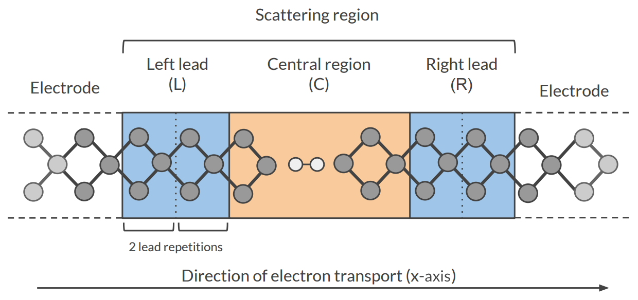
Our goal is to compute the transmission function \(T(E)\), which describes the rate at which electrons of energy \(E\) are transferred from the left electrode to the right electrode by propagating through the scattering region. From the transmission function we can calculate the electric current for given Bias Voltage \(V\) applied between the electrodes:
where \(f(E)\) is the Fermi-Dirac distribution function for a given temperature, and \(\mu_L\) (\(\mu_R\)) is \(\epsilon_F + eV/2\) (\(\epsilon_F - eV/2\)), \(\epsilon_F\) being the Fermi energy of the electrodes.
The transmission function \(T(E)\) can be computed from the Green’s function of our system.
The Green’s function \(G(E)\) of the scattering region is obtained solving the following equation:
where \(S\) is the overlap matrix, \(H\) is the Hamiltonian and \(I\) is the identity matrix. The Hamiltonian is composed as follows (L, C and R denote the left lead, the central region and the right lead respectively):
The two self-energies \(\Sigma_L\) and \(\Sigma_R\) model the two semi-infinite electrodes.
The transmission function \(T(E)\) can be calculated from the Green’s function \(G(E)\) and the so-called coupling matrices \(\Gamma_L(E)\) and \(\Gamma_R(E)\) (which are related to \(\Sigma_L\) and \(\Sigma_R\)):
See also
PhD Thesis of Mahdi Ghorbani-Asl (DFTB-NEGF developer)
Simulation workflow
The computation of the transmission function \(T(E)\) within the DFTB-NEGF formalism requires three individual simulations.
Tip
Use ADFInput (GUI) to set up your DFTB-NEGF calculation (see the DFTB-NEGF GUI tutorials)
- 1): DFTB leads calculation
A 1D-periodic DFTB calculation of the leads (StoreMatrices: yes, KSpace sampling 13):
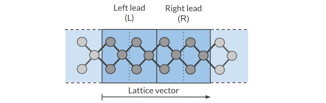
The Hamiltonian matrices \(H_L\) and \(H_{R}\) and the Fermi energy of the electrode \(\epsilon_F\) are computed in this calculation (\(H_L\), \(H_{R}\) and \(H_{LR}\) are also used to compute the surface Green’s functions \(g_L\) and \(g_R\) of the semi-infinite electrodes).
- 2): DFTB scattering-region calculation
A 1D-periodic DFTB calculation of the scattering region (StoreMatrices: yes, gamma-only, i.e., no KSpace sampling):
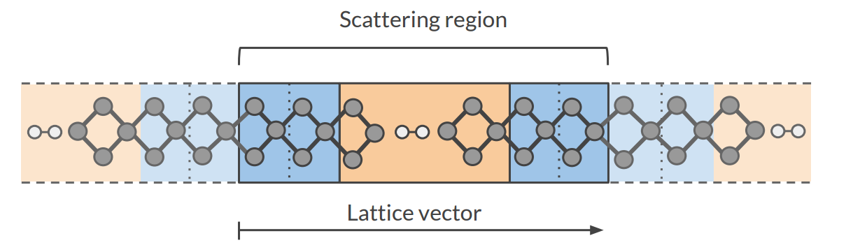
The Hamiltonian matrices \(H_{LC}\) and \(H_{RC}\) and \(H_{C}\) are computed in this calculation.
- 3): Conductance calculation
The Conductance program computes the NEGF transmission function \(T(E)\) using the Hamiltonians and overlap matrices from the previous two DFTB calculations.
Conductance input options
The Conductance program computes the transmission function using the NEGF approach. This is the input structure of the conductance program:
$AMSBIN/conductance <<EOF > conductance.out

  EnergyGrid
     Min value
     Max value
     Num value

  Files
     Leads       /path/DFTB_lead_filename.rkf
     Scattering  /path/DFTB_scattering_filename.rkf
  End

  Technical
     Eta                   value
     OverwriteLeads        [True|False]
     SetOffDiagonalToZero  [True|False]
  End

  end input
EOF
EnergyGrid- Type:
Block
- Description:
Energy grid for Transmission Function
Max- Type:
Float
- Default value:
5.0
- Unit:
eV
- Description:
Max Energy (relative to Fermi energy)
Min- Type:
Float
- Default value:
-5.0
- Unit:
eV
- Description:
Min energy (relative to Fermi energy)
Num- Type:
Integer
- Default value:
200
- Description:
Number of energy values in which the interval Min-Max is subdivided
Technical- Type:
Block
- Description:
options describing technical parts of the calculation
Eta- Type:
Float
- Default value:
1e-05
- Description:
To avoid poles of the Green’s function, a small imaginary number is added to the energy
overwriteLeads- Type:
Bool
- Default value:
Yes
- Description:
If true, Hamiltonians H_L and H_R are taken from the DFTB-leads calculation. If False, they are taken from the DFTB scattering-region calculation
setOffDiagonalToZero- Type:
Bool
- Default value:
Yes
- Description:
If true, H_LR and S_LR are explicitly set to zero. If False, they are taken from the DFTB scattering-region calculation.
Files- Type:
Block
- Description:
path of files
Leads- Type:
String
- Default value:
- Description:
Path (either absolute or relative) of the lead results file
Scattering- Type:
String
- Default value:
- Description:
Path (either absolute or relative) of the scattering region results
Miscellaneous remarks on DFTB-NEGF
You should make sure that your results are converged with respect to the number of lead repetitions; the results should not change significantly if you increase the number of lead repetitions.
It’s good practice to include at least one lead repetition in the central region.
The transmission function is computed at zero bias voltage. The zero-bias transmission function is then used for computing the electric current for non-zero bias voltage.