QM/MM: Inorganic linker in organic framework
Introduction
The hybrid engine is about applying different engines or settings to different regions. There are several different reasons to do so, but the most common one is performance. We will here look at inserting an organic linker in a system comprised of otherwise organic material.
Covalent organic frameworks
Covalent organic frameworks are built of small organic units. As anyone with a little bit of LEGO experience knows: there are infinite many ways to assemble small units. Understandably this a hot topic in material science. Organic systems are reasonably well described by the fast DFTB method. But what if we want to introduce a new inorganic block, for which DFTB fails?
Solution
Apply the fast method (DFTB) to most of the system, and only use DFT for the inorganic linker and its direct surrounding.
Setup with AMSinput
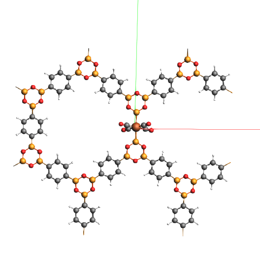
xyz file of the systemThis is what the structure looks like
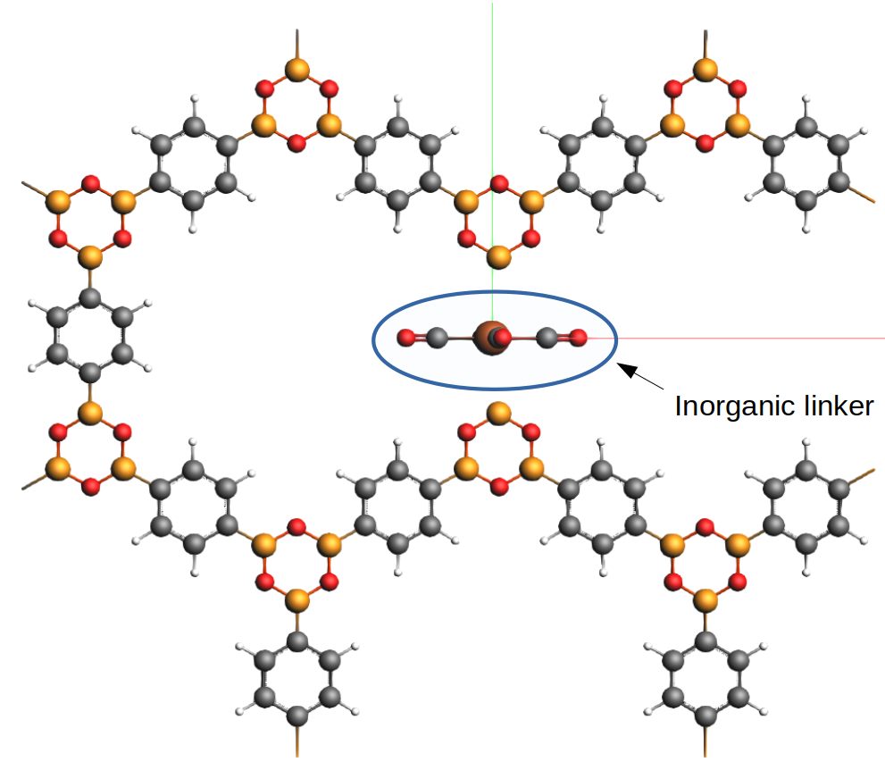
Most of the rings are made of organic material, except for the (inorganic) linker in the middle.
Define the QM region
In the QM region we want
our linker, and
the two directly neighboring organic rings.
Make the selection as shown in the picture:
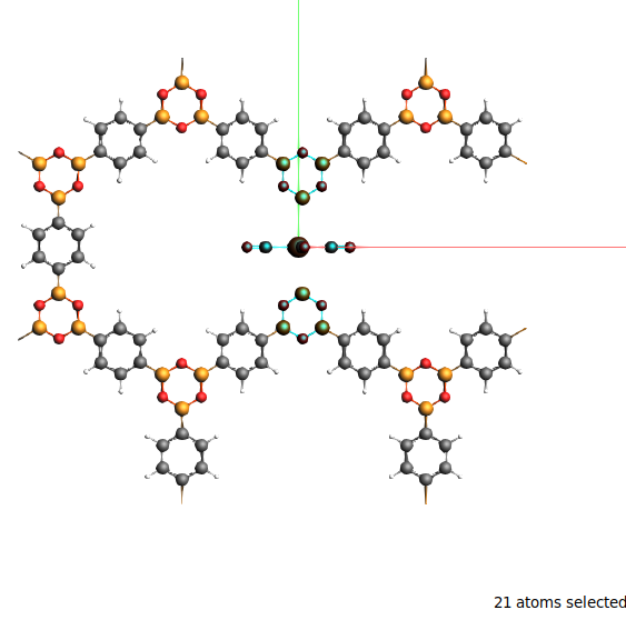
Using shift and click-dragging you can fairly easily select the three building blocks. In the end 21 atoms should be selected.
Tip
When there are bonds sticking out of the QM region, capping atoms will be added to the QM region to satisfy dangling bonds. The main rule is that you better not break very strong bonds, and it is recommended to use the menu item Selection → Make selection cappable. In this case nothing happens, as the selection was already sensible.
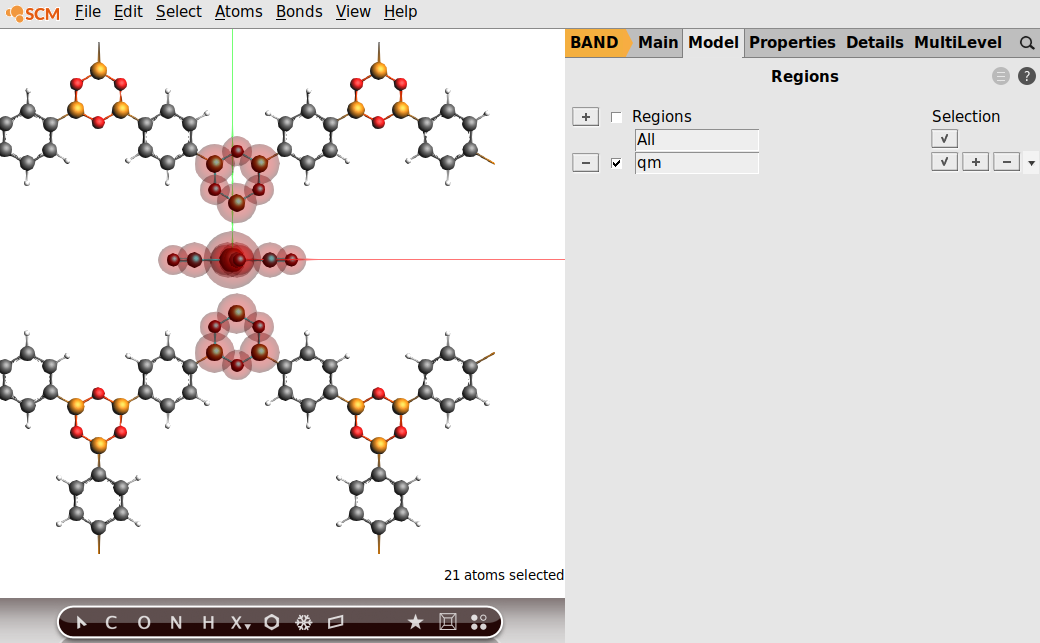
Now define the QM region. Use Model → Regions, and click on the plus region, and rename it to “qm”
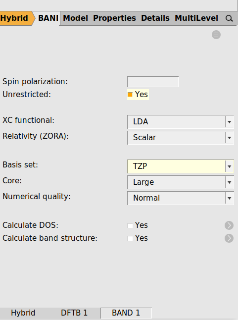
Setup the Hybrid Engine
Switch the engine from BAND to Hybrid. As you can see there is a Method being either “Energy Terms” or “QMMM”. See the hybrid engine documentation for more details.
The panel should look like this
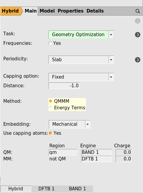
At the bottom you see the names of the two engines.
The panel should look like this
And that is it.
Results
Running this calculation will take quite a while. It is interesting to compare the results for three different calculations
The whole system with the cheap DFTB engine
The system with the Hybrid engine
The whole system with the BAND (DFT) engine
The first calculation is quick, the second one a bit more expensive, and the last one is a lot more expensive.
Here are the final geometries for the three calculations
The DFTB result displays a symmetric solution (plane tilted a bit) From exactly above the linker looks flat.
The Hybrid Engine produces an asymmetric solution
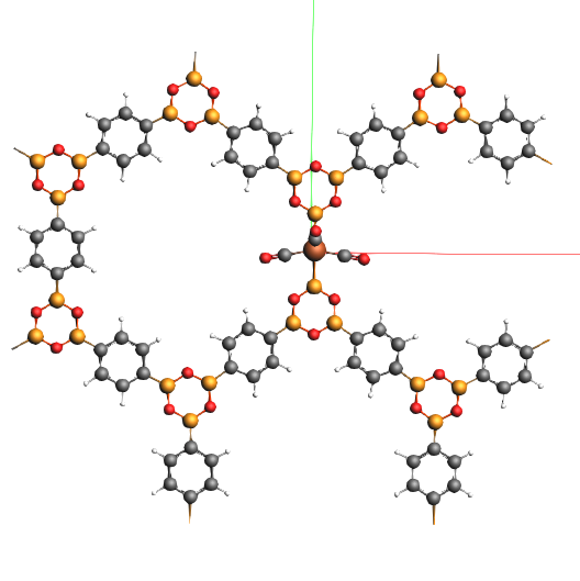
Also the Band engine shows the asymmetric solution.
Conclusions
For this system full DFTB gives very a different geometry as compared to DFT.
The hybrid result resembles closely the full DFT one (at one tenth of the time).
With the hybrid engine we can fix the inorganic part, wrongly described by the DFTB method.