Gate and Bias potentials
In this tutorial we will show how to include a Gate and Bias potentials in NEGF calculations.
- Start up ADFInputSwitch to BANDSelect Relativity → Scalar (important for heavy elements)Select Task → NEGFClick on
...to go to the NEGF panel (or click on Model → NEGF)
Download the lead and molecules .xyz files:
Note
The system studied in this tutorial is just a toy system.
Set up the system:
- 1. Select the file Li_lead.xyz as Lead2. Fill the central region with 4 layers of lead material3. Set the tips as shown in the figure4. Set the right and left lead offsets to -8.5 and 8.5 respectively5. Select Method → self-consistentImport the file CuAg.xyz by clicking on File → Import Coordinates...
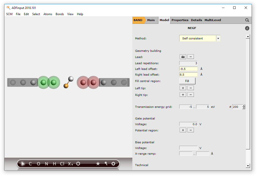
To apply a gate potential of 0.1 Volts for the CuAg molecule:
- 1. Select the CuAg molecule2. Click on the + next to Potential region3. Set the gate potential to 0.1 V

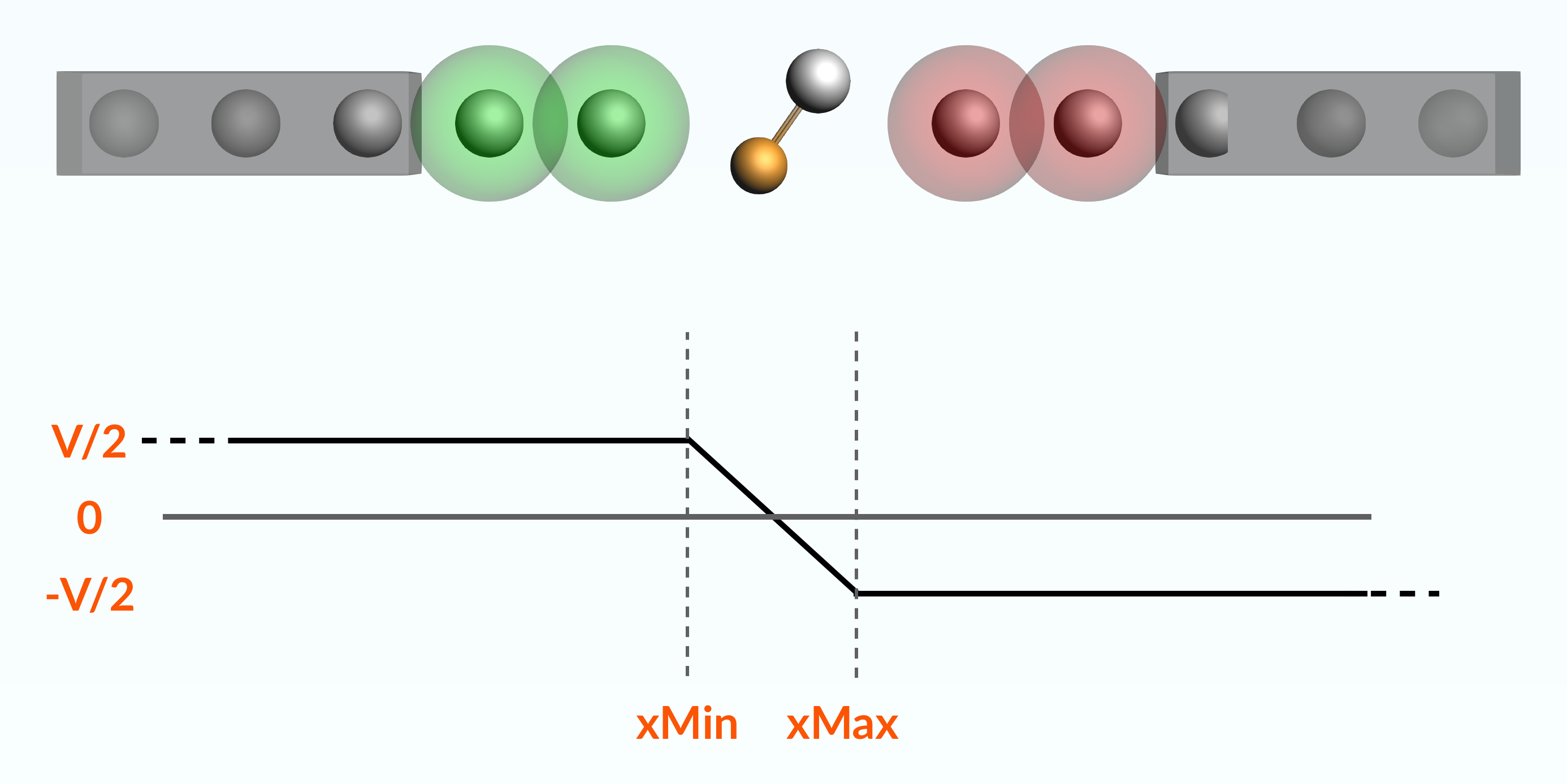
We will now apply a bias potential of 1 Volt, with a ramp-potential from -3.0 to 3.0 Bohr (see picture below):
Note
You can only apply a bias potential for the self-consistent and self-consistent + align NEGF methods
- 1. Set the bias potential Voltage to 1.02. Set the bias potential XMin and XMax to -3.0 and 3.0 respectively
we are now ready to run the calculation:
- Click on File → SaveRun the calculation with File → RunWait for the calculation to finish
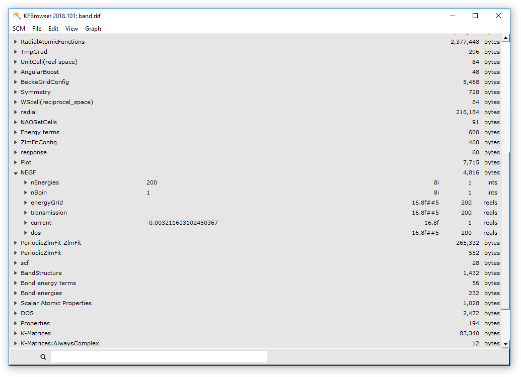
The current (in atomic units) is saved on the binary .rkf file.
- Click on SCM → KFBrowserActivate Expert mode by clicking on File → Expert modeClick on File → Related Files → band.rkfLook for the NEGF sectionClick on the small arrow next to the NEGF sectionThe current should be “-0.004158”
Tip
You can also extract this information using adfreport:
adfreport band.rkf "NEGF%current"
Warning
The Current vs Bias plot you can visualize with ADFSpectra is computed from a the transmission function at fixed bias, and it is therefore just an approximation of the real Current vs Bias characteristic. If you want to compute the actual Current vs Bias characteristic you have to run multiple calculations using different bias potentials.