Building Molecules
In the first tutorial you have learned how to construct a molecule by building it out of atoms. That may be a complex task for bigger molecules. ADFinput has other ways to build molecules.
The quickest is to search for a molecule inside ADFinput, and use it if it is available.
Another way is to search for the molecule on the Internet, and use either the xyz coordinates or the SMILES string
Or you can build it using the structure tool in ADFinput. As a more realistic example using the structure tool, you will build a small peptide chain. Then you will learn how to use the predefined metal complex structures. You will also learn how to set up your own structures library.
Finally, you can combine the crystal tools to cut molecular systems out of crystals. As an example we will make a sphere of Cu atoms.
Step 1: Start ADFinput
For this tutorial we again prefer to work in the Tutorial directory:
- cd $HOMEStart ADFjobsClick on the Tutorial folder iconStart ADFinput via SCM → New Input
Step 2: Search for ethanol
The quickest solution: search (and find) ethanol.
- Press ctrl/cmd-F to activate the search box (or click the search icon in the panel bar)Enter ‘ethanol’ as search text (without quotes)Click on the ‘Ethanol (ADF)’ matchRotate to get a good view
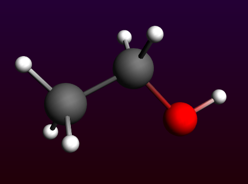
Your ethanol is ready. The (ADF) in the search results mean that the molecule has already been optimized by ADF, using the BP86 XC potential with a TZP basis set and small core.
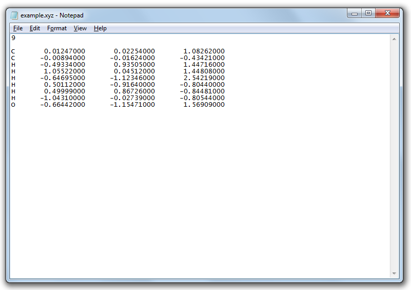
For the next demonstration we need a file with the xyz coordinates of ethanol. You can make such a file using the Export Coordinates option:
- Use the File → Export Coordinates... menu commandEnter ‘example.xyz’ as filenameClick Save
Step 3: Import XYZ for ethanol
To import a molecule if you have its structure as xyz file (with element types), you can either use the File → Import Coordinates... or the Edit → Paste command.
- Use the File → New menu command in ADFinputClick ‘No’ when asked if you want to save your changesClick in the ADFjobs window to activate itUse the Job → Refresh List menu command (or press F5)Click the triangle in front of example to show the example.xyz filectrl-double click on the .xyz file (listed in Local files)
This will open a text editor showing the contents of the the example.xyz file. The editor used depends on your operating system, but normally you will be able to select and copy text.
- Select all text in the ethanol.xyz fileCopy itClick in the ADFinput window to activate itPaste the xyz coordinates (ctrl/cmd-V or Edit → Paste)
You should again get the ethanol molecule, just as you have saved it.
Step 4: Import SMILES string
ADFinput can also interpret SMILES strings (via OpenBabel). As a demonstration, lets try again with Ethanol:
- Use the File → New menu command in ADFinputClick ‘No’ when asked if you want to save your changesOpen a web browserSearch for ethanol on wikipedia.orgAt the right side of the page, click the ‘Show’ link to show the SMILESCopy the SMILES string ( CCO )Click in the ADFinput window to activate itPaste the SMILES string (ctrl/cmd-V or Edit → Paste)Click in empty space in the drawing area to clear the selection
Again we have an ethanol molecule. SMILES strings do not contain the 3D structure, it was generated by OpenBabel and is NOT an ADF optimized structure. So normally the next step would be to pre-optimize with UFF (via the cog wheel), and to optimize the geometry with ADF.
SMILES strings work often, but there are also many examples where the resulting structure does not make sense.
Step 5: Build ethanol using the structure tool
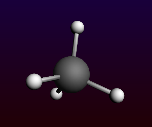
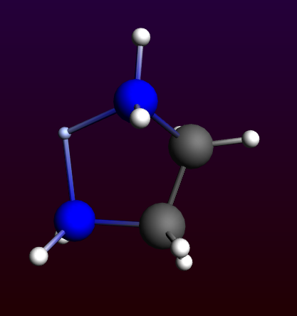
As a demonstration on how to use the structure tool, we start by building a methane molecule:
- Use the File → New menu command in ADFinputClick ‘No’ when asked if you want to save your changesSelect the C-toolClick somewhere in the drawing area to make a carbon atomSelect Atoms → Add Hydrogen , or faster: press the shortcut (ctrl-H or cmd-H)
If your cmd-H shortcut does not work (on a Mac), you probably need to fix your X11 preferences.
The next step is to add a methyl group, using the structures tool:
- Select the Structures tool → Alkyl Chains → Methyl structure (the structures tool is the benzene-like icon on the toolbar)
Notice that the button of the structures menu is glowing, which means that the structure-tool is in use.
- Double-click on one of the hydrogen atomsZoom out if needed (with right mouse button or mouse wheel)
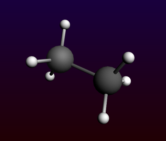
You will see that the hydrogen is replaced by a methyl group.
Note that:
- The methyl is orientated along the newly formed C-C bond and the new hydrogens point away from the existing ones.
- The double-clicked hydrogen is replaced by the carbon atom, since this atom is the ‘replacing’ atom. This atom is defined through having xyz-coordinates (0,0,0).
- The background glow moved from the ‘Structures’ tool to the ‘Pointer’ tool button; the ‘Pointer’ tool is active again.
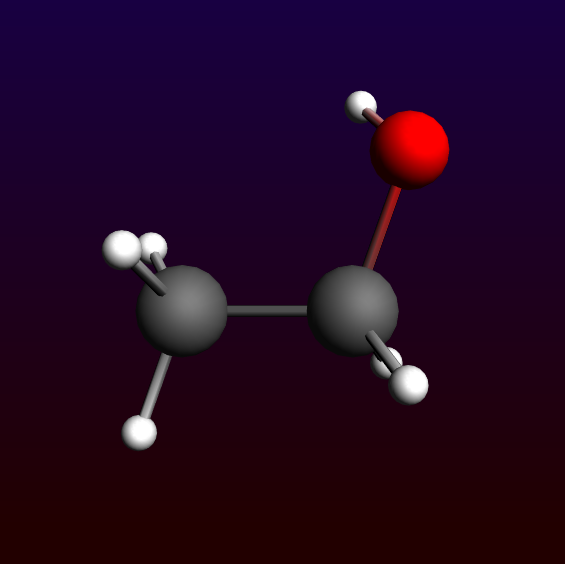
To create ethanol, we need to add a hydroxyl group:
- Select the Structures tool → Ligands → OH structureDouble-click on one of the hydrogen atoms
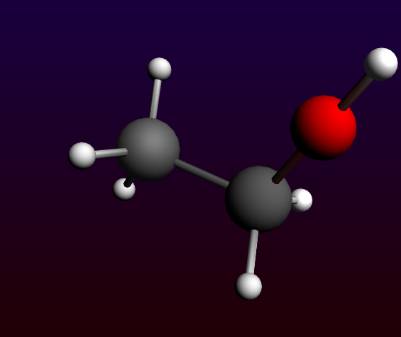
Again, the hydrogen is replaced by the structure. In this case, the oxygen replaces the double-clicked atom. The hydrogen is precisely aligned along the C-O bond and points away from the rest of the molecule. This shows you the very general way in which the structures will align according to the bonds in the original molecule and those in the structure. In this case, the hydroxyl group is not immediately orientated as it normally would be in an ethanol molecule:
- Pre-optimize: click on the cog wheel
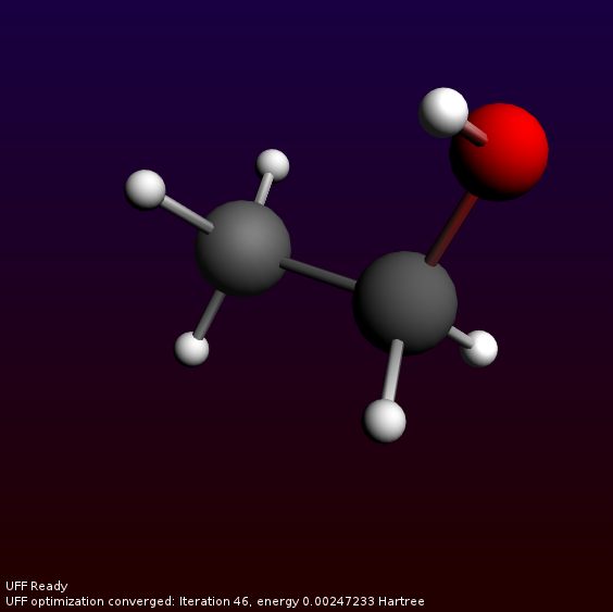
And again we have constructed an ethanol molecule.
ADFinput comes with a many predefined structures. Among them are some typical solvent molecules, so that you can easily add solvent molecules around your system. One of these ‘Solvent’ structures is Ethanol. Now add this molecule in empty space:
- Select the Structures tool → Solvents → Ethanol structureLeft-click in empty space near the hydroxyl group
Note that the oxygen is selected. Again, this oxygen is defined through having xyz-coordinates (0,0,0). Next we select the new molecule and orient it with the mouse to a reasonable position:
- Use the Select → Select Molecule menu command (or ctrl/cmd-M)Use the mouse to rotate and translate the ethanol molecule to your favorite orientation
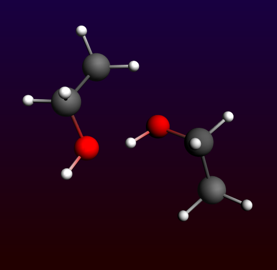
This way you can easily add explicit solvent molecules.
Step 6: Building a peptide chain using the structures tool
Now we will build a small peptide chain as another example using the structures tool.
- Select File → NewClick ‘No’ as we do not want to save the setupSelect the Structures tool → Amino Acids → AA Backbone structurePlace it in the drawing area
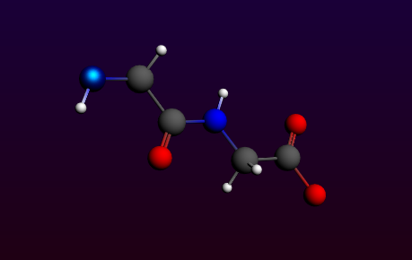
There appears a subunit (or actually two) of a basic peptide chain. Notice that one of the atoms is selected, namely the terminal nitrogen. This atom is, again, the ‘replacing’ atom. In order to extend the peptide backbone, you now have to choose the right atom to be replaced. The obvious choice is the (non double-bonded) terminal oxygen.
- Click in empty space to deselect the nitrogenPress the space bar, which activates the last used option of the ‘Structure’ tool (‘AA backbone’ here).Double click on the terminal oxygen.You may want to use View → Reset View.
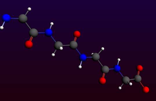
In a similar fashion, you can now replace the hydrogens on the backbone by amino acid side groups of your choice. These can be found in the Structures tool → Amino Acid → AA Side Groups sub-menu.
Step 7: Metal complexes and ligands
In the sub-menu ‘Metal Complexes’ you can find a set of predefined complexes corresponding to commonly encountered geometries. Furthermore, there are a number of ligands to be found, which can be easily used with these metal complexes.
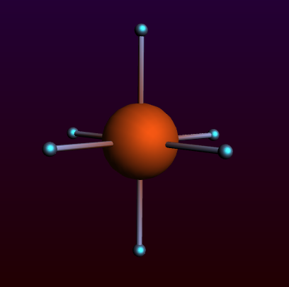
Predefined Metal Complex Geometries
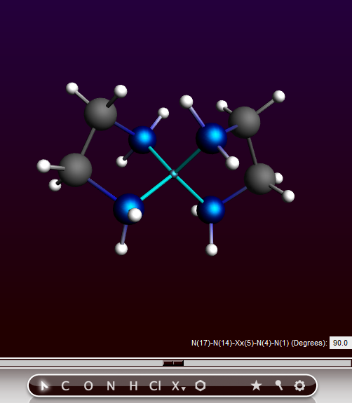
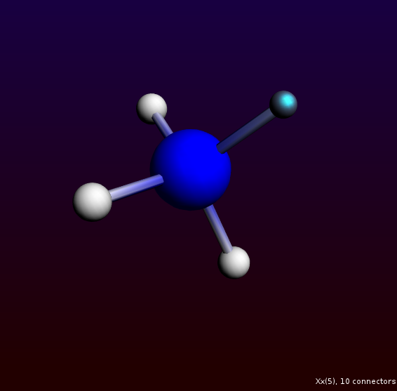
Select the File → New command Click No (do not save changes) Select Structures tool → Metal Complexes → ML6 Octahedral tool and place it in the drawing area
Notice that six dummy (“Xx”) atoms have been placed around the metal center in an octahedral fashion.
- Select one of the dummy atoms by clicking on itSelect Select → Select Atoms Of Same Type menu command
The Ligands structure sub-menu contains a number of ligands which can be used to replace the dummy atoms. The Structure menu can, however, also be reached via the Atoms menu.
- Select the Atoms → Replace By Structure → Ligands → CN commandClick in empty space to clear the selectionReset the View if needed
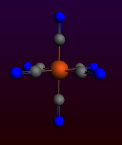
Notice that all dummy atoms in the selection are replaced by CN ligands.
Bidentate Ligands
In order to use the bidentate ligands, we must start with a bare metal center.
- Select the File → New commandClick No (do not save changes)Place an iron atom in the drawing area (click the X button in the toolbar to get a menu with all elements)Select the Structures tool → Ligands → Bidentates → Ethylenediamine structureDouble-click on the metal atom
You can see that, in this case, the metal atom is not replaced by an atom of the structure, contrary to previous experience, but that the bidentate ligand is simply attached to the central metal atom.
This works because the ‘replacing’ atom in all bidentate structures is a dummy atom, which has the property that it won’t replace an existing atom. The metal atom will simply take over the bonds that existed on the dummy atom in the structure. You can easily verify this when you would place the structure in empty space. Other multidentate ligands are defined in a similar fashion.
- Press space bar and double-click on the metal atom
Notice that the second ligand appears opposite the existing one.
Modifying the Plane Angle
To change the relative orientation of two bidentate ligands, we can change the plane angle. The planes are defined by two sets of three atoms, the central one being present in both sets. In this case this will, of course, be the metal atom.
- Select, in order, the two nitrogens on ligand one, the metal atom, and the nitrogens on the second ligand.Change the plane angle to 90 degrees using the slider
In this way, you can easily change the environment around the metal from square planer to tetrahedral. This feature works as long as you choose the atoms in right order, and if the defined planes can freely rotate relative to each other.
Step 8: Your own structures library
You can make your own structure library very easily.
By default, user defined structures will be stored in the .scm_gui/Structures directory.
Defining your structures
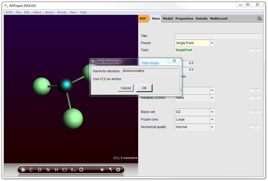
To be able to actually use the structures as described earlier, it is necessary to define one of the atoms as having xyz-coordinates (0,0,0). This will then be the atom that will actually appear at the spot of the atom that is replaced by the structure. If you use the Save As Structure command this will be done for you.
- Select the File → New commandClick No (do not save changes)Build methaneReplace three of the hydrogens by chloride atoms and pre-optimizeDelete the remaining hydrogenSelect the central carbon atomUse the Structures tool → Save As Structure ... commandEnter a name like trichloromethylNote that the selected atom (currently the C atom) will be used as anchor
The new structure will appear in the structures menu and can be directly used.
Using dummy atoms
Dummy (“Xx”) atoms are treated differently when used in structures. A dummy atom will not replace an existing atom when it is defined as the ‘replacing atom’. Instead, the double-clicked atom will remain and will accept the bonds that the dummy atom had in the structure.
- Build a methane moleculeReplace the carbon atom by a nitrogen atomSelect one of the hydrogens and replace it by a dummy atom (the Xx atom type, in the periodic system)Select the dummy atomSave the structure using the Structures tool → Save As Structure ... command
Now you can select the structure from the structures menu and directly use it.
- Select your new structure from the structures menuDouble-click on one of the hydrogens
Notice that the hydrogen atom is not removed and that the NH3 group is attached to it. Similar behavior has been demonstrated with the bidentate ligands, where the dummy atoms are also used.
If you want to clean up your structures, you can use the Structures tool → Manage Structures... command. If you use it, ADFjobs will open and show the contents of your Structures directory. As the structures are just (simplified) .adf files, you can open them using ADFinput. And using ADFjobs you can rename them or delete them.
Step 9: A sphere of Cu atoms, cut out of the crystal
We start making a Cu crystal, using a super cell so we have many real Cu atoms.
To build the crystal, we need to use the periodic tools. These will work only for programs supporting periodicity, like DFTB.
- Start ADFinput (or use File → New in the currently open ADFinput window)Switch to DFTB mode (panel bar ADF → DFTB)Select ‘Periodicity: Bulk’Edit → Crystal → Cubic → fccClick OK in the pop-up-windowEdit → Crystal → Generate Super Cell...Click OK in the pop-up-windowUncheck View → Periodic → Repeat Unit Cells, so only one unit cell will be shown
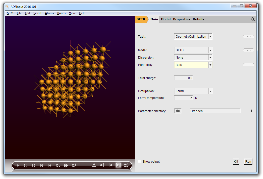
Now we have a block of Cu, with explicit Cu atoms (that is using a super cell). Next we will center this block, and select a sphere of atoms around the origin.
- Make sure the origin is in the center of the block: Edit → Set OriginSelect → Select Atom Close To OriginSelect → Select Within RadiusClick OK
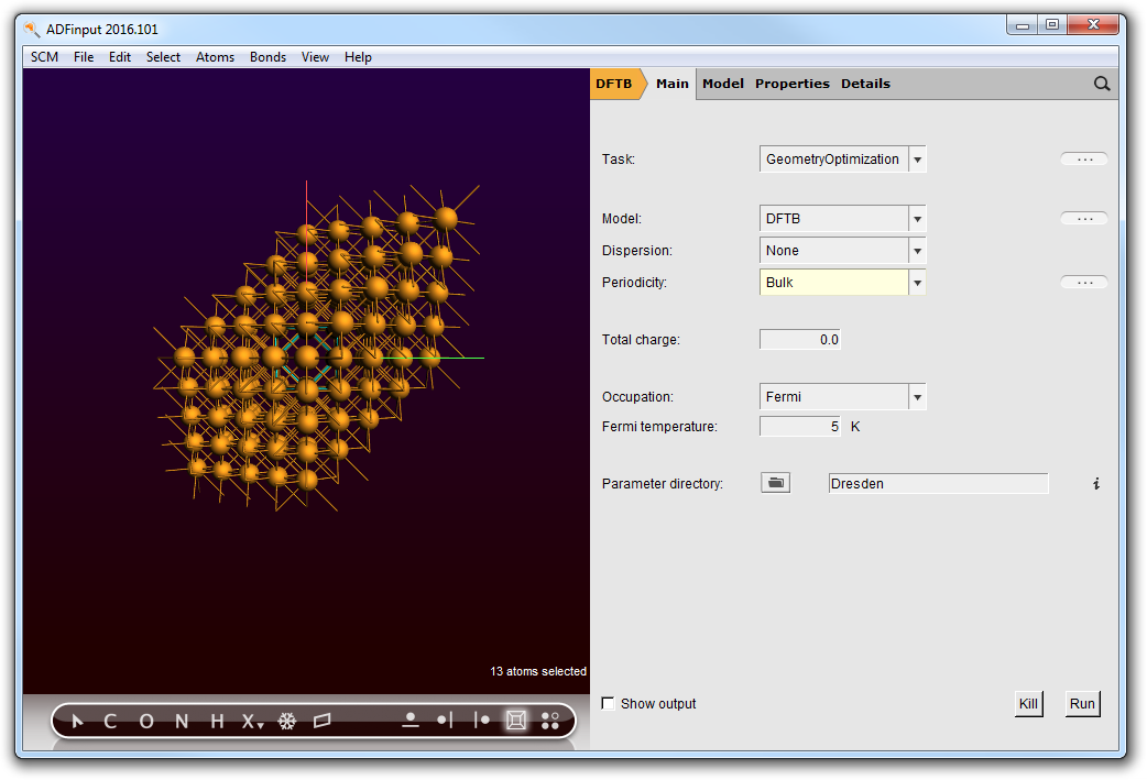
- Select → Invert SelectionPress the Backspace key to delete the selected atomsIf it does not respond: click once in the drawing area to focus on it, and press the Backspace key againSwitch to ADF: panel bar DFTB → ADFRotate a little
As you can see, you have a (very small) sphere consisting of Cu atoms in the molecular ADF program:
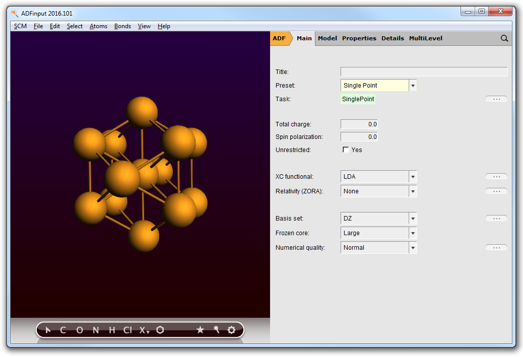
Obviously, by making a bigger super-cell and selecting atoms within a larger radius you can make bigger spheres.
Step 10: A carbon nanotube
A small piece of nanotube is included in the molecule database, so you can just search for it and use it. However, typically one wants some specific nanotube structure. And make it infinite (periodic in one dimension). This can conveniently be done by importing the structure as found on the web:
- Use a web browser to go to the TubeGen nanotube structure generatorRequest CIF format as output, leave other options at the default valuesClick generate
In the browser windows we get the nanotube structure in CIF format, something like the following:
data_nanotube

_audit_creation_method       '(3,3) Nanotube -- TubeGen 3.3, J T Frey, University of Delaware'

_cell_length_a         7.4762
_cell_length_b         7.4762
_cell_length_c         2.4643
_cell_angle_alpha     90.00
_cell_angle_beta      90.00
_cell_angle_gamma    120.00

_symmetry_space_group_name_H-M   'P 1'
_symmetry_Int_Tables_number       1

loop_
_atom_site_label
_atom_site_fract_x
_atom_site_fract_y
_atom_site_fract_z
C         0.7762    0.5000    0.0000
C         0.8138    0.7061    0.0000
C         0.7762    0.7762    0.5000
C         0.6077    0.8138    0.5000
C         0.5000    0.7762    0.0000
C         0.2939    0.6077    0.0000
C         0.2238    0.5000    0.5000
C         0.1862    0.2939    0.5000
C         0.2238    0.2238    0.0000
C         0.3923    0.1862    0.0000
C         0.5000    0.2238    0.5000
C         0.7061    0.3923    0.5000
Next we want to get this structure into ADFinput:
- Select the CIF information in your browserCopyStart ADFinputEdit → Paste.View → AxesRotate to get a good view
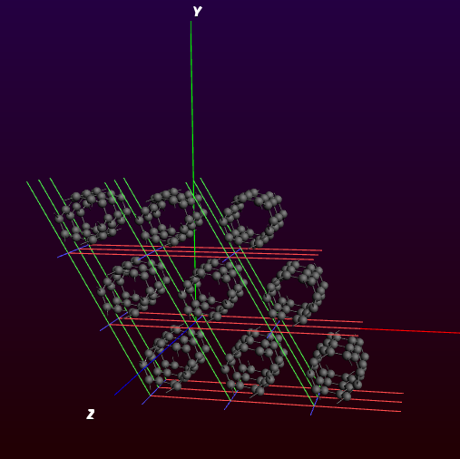
We see a piece of nanotube, repeated in all directions. Actually nine nanotubes are visible.
Notice that the nanotubes are oriented along the Z-axes.
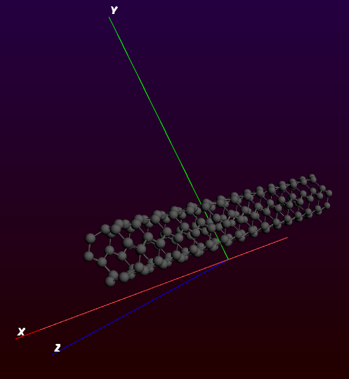
The GUI can handle one-dimensional systems. However, in case of a one dimensional system (a chain) the lattice vector is always along the X direction. So to change our nanotube in a nice periodic one-dimensional structure we need to rotate it (including the lattice vectors) such that the tube is along the X-axes.
- Use the Edit → Rotate 90 menu command to make the nanotube lie along the X-axes (hint: rotate around the Y-axes)Switch to a one-dimensional system (chain)
The Rotate 90 command did not only rotate the coordinates of the atoms, but also the lattice vectors. Now we have a small piece of nanotube (remember it already is repeated 3 times for visualization purposes). This might be sufficient for your purposes, but it is easy to make a bigger piece:
- Edit → Crystal → Generate Super CellClick OK to repeat the unit cell 5 times
Switch to some non-periodic code (like ADF) if you wish to treat this piece of nanotube without infinite symmetry.