Modeling phosphorescent lifetimes of OLED emitters

NOTE: this example was made with ADF2014.10. Screenshots and results may differ

In organic light-emitting diodes (OLEDs), phosphorescent dyes increase the maximum theoretical efficiency from 25% to 100% with respect to fluorescent dyes. To model the spin-forbidden phosphorescence from the triplet state to the singlet ground state, T1 → S0, spin-orbit coupling must be included in TDDFT calculation (SOC-TDDFT). With ADF it is possible to calculate phophorescent lifetimes with SOC-TDDFT, as explained in this guided example for a famous OLED emitter, the 5d transition metal complex Ir(ppy)3.

Example input and output files

While this example is self-contained, it is still helpful to download the sample input and output files.

Essentially the procedure for predicting phosphorescent lifetimes consists of two steps:

  1. Optimization of the lowest triplet state (T1)
  2. SOC-TDDFT calculation at the optimized T1 geometry
1. Optimization of the lowest triplet state (T1)

Since the T1 state is the lowest in the triplet manifold, the T1 geometry can be optimized just as a regular ground state, but with triplet spin multiplicity. Usually the triplet state is lower in symmetry than the ground state, so it is recommended to switch off symmetry (NoSym). See also the recent paper by Gonzalez-Vazquez et al. where the importance of relaxing the T1 state is discussed.

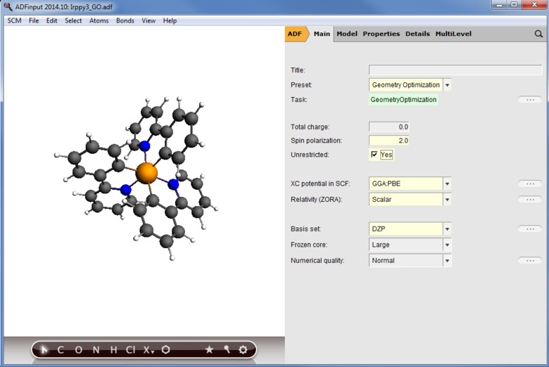
In the example input file we optimize the triplet state with the PBE functional, a DZP basis set (defaults to TZP for Ir), scalar ZORA and otherwise default settings (Normal integration, large core). You can open the .adf file directly with the GUI.
To set up your own triplet geometry optimization for a different organometallic complex, you can either copy and paste the relevant parts from the command line example, or you can follow these steps in the GUI:

Open ADFJobs
SCM → New Input
Build or import your structure
In the Main menu options panel:
Preset → Geometry Optimization
Spin-polarization → 2.0
Tick the 'yes' box next to Unrestricted:
XC potential in SCF: → select the desired XC functional (e.g. PBE or B3LYP)
Relativity (ZORA): → Scalar
Basis set: → DZP (or use TZP or TZ2P for higher accuracy)
You can also use a smaller frozen core and/or increase Numerical quality

GeometryOptimization_T1_state_Irppy3

2. Relativistic (ZORA) spin-orbit coupling TDDFT calculation

To calculate the phosphorescent lifetime from the T1 state, a SOC-TDDFT calculation is done on the triplet ground state, from the electronic singlet ground state on that geometry.
In ADF you can do a fully self-consistent SOC-TDDFT calculation (see the input and output files Irppy3_SOC), or do a perturbative SOC (pSOC) calculation (Irppy3-pSOC). Several groups have obtained great insight in phosphorescence behavior by using (pSOC). A pSOC calculation offers insight in the underlying singlet and triplet contributions to the excitations, which can aid with designing ligands which yield better emission properties. Similarly, insight in singlet and triplet contributions may also be achieved by performing a full SOC calculati on employing a scalar-relativistic fragment of the full molecule, as explained further below.

Typically the lowest 3 states of the spin-orbit coupling TDDFT calculation are important which resemble the 3 states in a triplet state.
There will be a small energy difference between the three states because of spin-orbit coupling, the so called zero-field splitting (ZFS). Oscillator strengths and radiative lifetimes for each excitation are printed in the output, they are related according to:

1/τ = 2(ΔE)2 f/c3 

This equation is in atomic units (a.u.: e=1,i m=1, h/2pi=1). Note that in a.u. c = 137.036, and 1 a.u. of time = 2.419E-17 sec. ΔE is the excitation energy, f the oscillator strength (both in a.u.!)

Note that in this example moderately-sized basis sets have been used (all electron TZP for Ir and DZP for H,C,N). For this particular system that is sufficient, but one may need larger basis sets (TZ2P, QZ4P) for other systems.

To set up a SOC-TDDFT for your own phosphorescent dye, start from the command line examples, or follow these steps in the GUI.

Update the triplet geometry when the calculation is finished
In the Main menu options panel of ADFInput:
Preset → Single Point 
Spin-polarization → 0.0
Make sure the 'yes' box is NOT ticked
XC potential in SCF: → select the desired XC functional (e.g. BP or B3LYP)
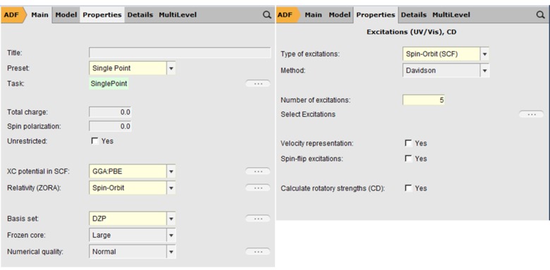
Relativity (ZORA): → Spin-Orbit
Basis set: → DZP (defaults to TZP for Ir)
Properties → Excitation, CD
Type of excitations → Spin-Orbit (SCF)
Number of excitations → 5

SOC-TDDFT_Irppy3

Singlet and triplet contributions to the spin-orbit coupled excited states

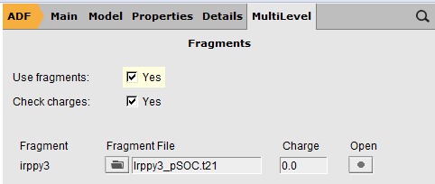
If you want to analyze the singlet and triplet contributions, you should first run a scalar relativistic TDDFT calculation (e.g. 20 states) by setting Relativity (ZORA): → Scalar and Type of excitations → SingletAndTriplet (Irppy3_SR). Then you perform the same SOC-TDDFT as above, but you enter ‘STCONTRIB’ as a keyword (Details → User Input in the GUI) and you use the Irppy3_SR calculation as a fragment (see Irppy3_SOC_STCONTRIB example files).

STCONTRIB_SOCTDDFT


Output: phosphorescent lifetimes

To have an idea what is in the output file, without actually running the calculations, just open the example output files either with your favorite text editor or with the ADFGUI.

If you open it with ADFGUI, it will take you to the output browser. You can search for ‘tau’ to jump straight to the phosphorescent lifetimes.

Remember that tau and krad are interrelated: 1/τ = 2(ΔE)2 f/c3, in a.u.

 no.     E/a.u.        E/eV      f           tau/s        Symmetry
 ------------------------------------------------------------------
   1:     0.06868      1.86882   0.5724E-07   0.1153      A           
   2:     0.06908      1.87966   0.2229E-02   0.2926E-05  A           
   3:     0.06914      1.88139   0.2607E-02   0.2498E-05  A           
   4:     0.07017      1.90956   0.4649E-03   0.1360E-04  A           
   5:     0.07401      2.01405   0.2186E-03   0.2599E-04  A           

 tau: electric dipole radiative lifetime (in seconds)

If you scroll up from the radiative lifetimes you will find the major MO → transitions, and if you have used STCONTRIB with a scalar-relativistic fragment, the major contributions to those excitations from the singlet and triplet states in an uncoupled picture. Further insight in the effect of spin-orbit coupling on the MOs may be obtained by looking at ADF Levels (from the SCM main menu in the GUI).

A cheaper alternative (ca. 5 times faster) to full spin-orbit coupling calculations is the approximate, perturbative SOC scheme. This seems a reasonable approximation for phosphorescence radiative lifetime calculations, as for instance found in this highlight on OLED phosphorescence.

Perturbative SOC: spin-orbit coupling matrix (SOCME)

Example files are also included for a perturbative SOC calculation (Irppy3_pSOC). You will see that the phosphorescent lifetimes with pSOC, even with 80 states, are slightly longer with perturbative SOC than with fully self-consistent SOC.

To print the full spin-orbit coupling matrix, include PRINT SOMATRIX in your input (or tick ‘Spin-orbit coupling matrix in the GUI in the Excitation panel). Starting from ADF2017 the output will then also show a summary of the spin-orbit coupling matrix elements (SOCME) as root-mean square average.

SOCME ADF

These SOCMEs are important parameters for designing phosphorescent OLED emitters:  optimize internal conversion to T1 from the singlet exciton and minimize non-radiative decay (see Highlight on intersystem crossing.
Likewise, SOCMEs are useful figure of merits to design better TADF (thermally activated delayed fluorescence) emitters (see e.g. Bredas et al., J. Am. Chem. Soc. 139, 4042−4051 (2017)) and our TADF tutorial.

Optimizing TADF tutorial

Accuracy considerations of the phosphorescent lifetime predictions

The use of the XC functional is relevant for the accuracy of the results. In this example the PBE functional was used. One can also use hybrids by chosing the appropriate fucntional in the GUI (main panel) or setting the appropriate functional in the XC block in your input.
Hybrid functionals such as B3LYP seem to give quite good results, however, they will take more CPU time. To reduce the time in such a B3LYP calculation, without much loss of accuracy, you may use a bit coarser integration, ‘Becke Normal’ as was used in this example. You may even use frozen cores, although this is not strictly correct for hybirds.

We find good agreement (K. Mori et al., Phys. Chem. Chem. Phys. 16, 14523-14530 (2014)) between calculated and experimental radiative lifetimes for various phosphorescent transition metal complexes when we use the following settings:

  • Strict presets: ExactDensity, FullSCF, gradients 1e-4, SCF 1e-6, Becke ‘Good’ grid, DEPENDENCY bas=1e-3
  • All-electron DZP basis (defaults to TZP for transition metals)
  • Optimize T1 with reduced symmetry, or NoSym
  • B3LYP functional
  • 20 excitations for the SR-TDDFT calculation, 4 for the STCONTRIB SOC-TDDFT calculation

Further accuracy considerations may be to employ a larger basis set (TZ2P) and to include continuum solvation with COSMO. Solvation effects may especially improve the accuracy of ZFS and lifetime calculations (see the paper by Mori et al.).

In a recent study by Younker and Dobbs, a good correlation is found between calculated and observed phosphorescent rates of Ir(III) complexes when using a pSOC-TDDFT approach with B3LYP on the BP86-optimized singlet ground state.

References

Excitations including spin-orbit coupling:
F. Wang, T. Ziegler, E. van Lenthe, S.J.A. vand Gisbergen and E.J. Baerends, The calculation of excitation energies based on the relativistic two-component zeroth-order regular approximation and time-dependent density-functional with full use of symmetry. J. Chem. Phys. 112, 204103 (2005)

Perturbative approach to include spin-orbit coupling:
F. Wang and T. Ziegler, A simplified relativistic time-dependent density-functional theory formalism for the calculations of excitation energies including spin-orbit coupling effect , J. Chem. Phys. 113, 154102 (2005)

Request a demo to try for yourself!